How to Use Customs pcb: Examples, Pinouts, and Specs
Introduction
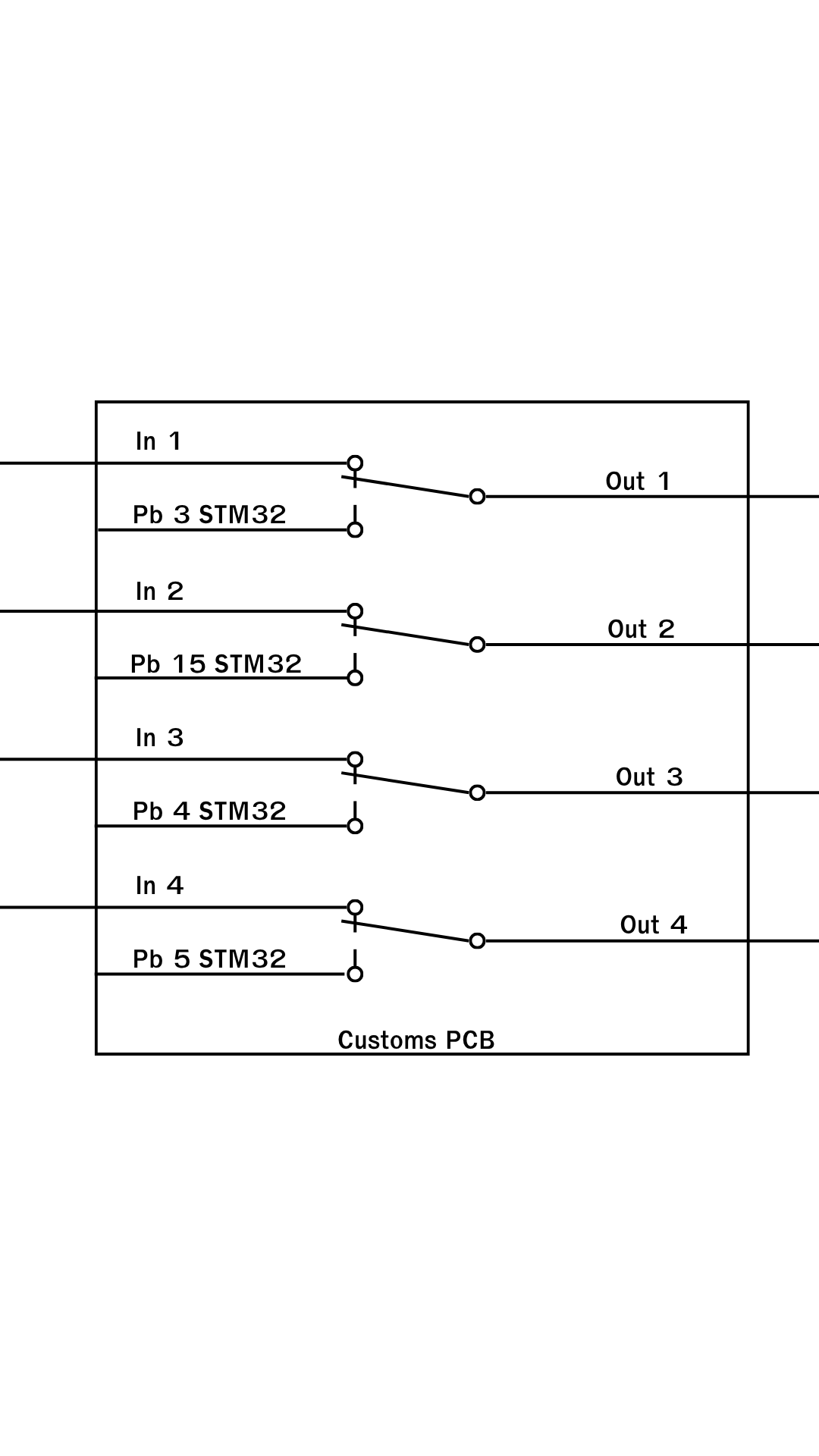
A Customs PCB is a printed circuit board designed to meet specific requirements for a particular application. Unlike standard off-the-shelf PCBs, custom PCBs allow for tailored circuit layouts, component placements, and unique design features to optimize performance for a specific use case. These boards are widely used in industries such as consumer electronics, automotive, medical devices, and industrial automation.
Explore Projects Built with Customs pcb

Explore Projects Built with Customs pcb
Common Applications and Use Cases
- Prototyping and Product Development: Ideal for testing and refining new electronic designs.
- Industrial Automation: Custom PCBs are used in machinery and control systems for optimized performance.
- IoT Devices: Tailored PCBs for compact and efficient IoT hardware.
- Medical Equipment: High-precision PCBs for diagnostic and monitoring devices.
- Consumer Electronics: Custom PCBs for unique product designs, such as wearables or smart home devices.
Technical Specifications
The technical specifications of a Customs PCB depend on the design and application. Below are general parameters that can be customized:
General Specifications
| Parameter | Description |
|---|---|
| Manufacturer | Customs PCB |
| Part ID | Customs PCB |
| Material | FR4 (standard), Rogers, Aluminum, or other materials based on requirements |
| Layers | 1 to 16+ layers (depending on complexity) |
| Thickness | 0.6mm to 3.2mm (customizable) |
| Copper Thickness | 1oz to 3oz (customizable) |
| Surface Finish | HASL, ENIG, OSP, or other finishes |
| Solder Mask Color | Green, Blue, Black, Red, White, or custom |
| Silkscreen | White, Black, or custom |
| Operating Temperature | -40°C to 85°C (or higher for specialized applications) |
Pin Configuration and Descriptions
Custom PCBs do not have a fixed pin configuration, as the layout is designed based on the specific application. However, the following table provides an example of a typical pin header configuration for a custom PCB designed for microcontroller-based applications:
| Pin Number | Pin Name | Description |
|---|---|---|
| 1 | VCC | Power supply input (e.g., 3.3V or 5V) |
| 2 | GND | Ground connection |
| 3 | GPIO1 | General-purpose input/output pin |
| 4 | GPIO2 | General-purpose input/output pin |
| 5 | TX | UART transmit pin |
| 6 | RX | UART receive pin |
| 7 | SDA | I2C data line |
| 8 | SCL | I2C clock line |
| 9 | MOSI | SPI master-out, slave-in |
| 10 | MISO | SPI master-in, slave-out |
| 11 | SCK | SPI clock |
| 12 | RESET | Reset pin |
Usage Instructions
How to Use the Component in a Circuit
- Design the Schematic: Use PCB design software (e.g., KiCad, Eagle, or Altium Designer) to create the circuit schematic. Ensure all components are correctly placed and connected.
- Layout the PCB: Arrange the components on the PCB layout, considering factors like signal integrity, thermal management, and manufacturability.
- Manufacture the PCB: Send the design files (Gerber files) to a PCB manufacturer. Specify the material, layer count, thickness, and other parameters.
- Assemble the PCB: Solder the components onto the PCB manually or using automated assembly equipment.
- Test the PCB: Verify the functionality of the PCB by testing it in the intended application.
Important Considerations and Best Practices
- Power and Ground Planes: Use dedicated planes for power and ground to reduce noise and improve stability.
- Trace Width and Spacing: Ensure traces are wide enough to handle the required current and maintain proper spacing to avoid shorts.
- Thermal Management: Use thermal vias and heat sinks for high-power components.
- Signal Integrity: Minimize trace lengths for high-speed signals and use impedance-controlled traces if necessary.
- Design for Manufacturability (DFM): Follow DFM guidelines to ensure the PCB can be manufactured without issues.
Example: Connecting a Custom PCB to an Arduino UNO
If your custom PCB is designed to interface with an Arduino UNO, you can use the following example code to communicate with it via I2C:
#include <Wire.h> // Include the Wire library for I2C communication

#define CUSTOM_PCB_ADDRESS 0x08 // I2C address of the custom PCB

void setup() {
  Wire.begin(); // Initialize I2C communication
  Serial.begin(9600); // Start serial communication for debugging
  Serial.println("Initializing communication with Custom PCB...");
}

void loop() {
  Wire.beginTransmission(CUSTOM_PCB_ADDRESS); // Start communication with the PCB
  Wire.write("Hello"); // Send data to the PCB
  Wire.endTransmission(); // End the transmission

  delay(1000); // Wait for 1 second

  Wire.requestFrom(CUSTOM_PCB_ADDRESS, 6); // Request 6 bytes from the PCB
  while (Wire.available()) {
    char c = Wire.read(); // Read each byte
    Serial.print(c); // Print the received data to the Serial Monitor
  }
  Serial.println(); // Print a new line
  delay(1000); // Wait for 1 second before the next loop
}
Troubleshooting and FAQs
Common Issues Users Might Face
PCB Does Not Power On:
- Cause: Incorrect power supply voltage or polarity.
- Solution: Verify the power supply voltage and polarity match the PCB requirements.
Short Circuits:
- Cause: Solder bridges or incorrect component placement.
- Solution: Inspect the PCB for solder bridges and ensure components are correctly placed.
Signal Noise or Interference:
- Cause: Poor grounding or improper trace layout.
- Solution: Use a dedicated ground plane and minimize high-speed signal trace lengths.
Components Overheating:
- Cause: Insufficient thermal management.
- Solution: Add thermal vias, heat sinks, or cooling fans as needed.
Communication Failure with Microcontroller:
- Cause: Incorrect pin connections or mismatched communication settings.
- Solution: Double-check the pin connections and ensure the communication protocol settings (e.g., baud rate, I2C address) are correct.
Solutions and Tips for Troubleshooting
- Use a multimeter to check for continuity and verify power supply connections.
- Inspect the PCB under a magnifying glass or microscope to identify soldering issues.
- Use an oscilloscope to analyze signal integrity and detect noise or interference.
- Refer to the PCB design files to verify the layout and connections.
By following this documentation, users can effectively design, assemble, and troubleshoot their custom PCBs for a wide range of applications.