How to Use DFRobot DC/DC Step Down Convertor: Examples, Pinouts, and Specs
Introduction
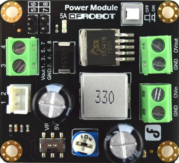
The DFRobot DC/DC Step Down Converter (Part ID: DFR0205) is a compact and efficient device designed to reduce a higher DC voltage to a lower DC voltage. This step-down (buck) converter is ideal for applications requiring stable and efficient power management, such as powering microcontrollers, sensors, and other low-voltage devices from a higher voltage source.
Explore Projects Built with DFRobot DC/DC Step Down Convertor


Explore Projects Built with DFRobot DC/DC Step Down Convertor
Common Applications
- Powering Arduino boards, Raspberry Pi, and other microcontrollers.
- Supplying stable voltage to sensors and modules in robotics projects.
- Battery-powered systems requiring voltage regulation.
- General-purpose DC voltage regulation in electronic circuits.
Technical Specifications
The following table outlines the key technical details of the DFRobot DC/DC Step Down Converter:
| Parameter | Value |
|---|---|
| Input Voltage Range | 6V to 23V DC |
| Output Voltage Range | 3V to 12V DC (adjustable) |
| Maximum Output Current | 3A |
| Efficiency | Up to 95% |
| Dimensions | 22mm x 17mm x 4mm |
| Weight | 3g |
Pin Configuration and Descriptions
The DFRobot DC/DC Step Down Converter has the following pin configuration:
| Pin Name | Description |
|---|---|
| VIN | Input voltage pin. Connect to the higher DC voltage source (6V to 23V). |
| GND | Ground pin. Connect to the ground of the power source and the load circuit. |
| VOUT | Output voltage pin. Provides the regulated lower DC voltage (3V to 12V). |
Usage Instructions
How to Use the Component in a Circuit
Connect the Input Voltage (VIN):
- Attach the VIN pin to the positive terminal of your DC power source (6V to 23V).
- Connect the GND pin to the ground of your power source.
Adjust the Output Voltage:
- Use the onboard potentiometer to adjust the output voltage.
- Turn the potentiometer clockwise to increase the output voltage and counterclockwise to decrease it.
- Use a multimeter to measure the output voltage at the VOUT pin while adjusting.
Connect the Load:
- Attach the VOUT pin to the positive terminal of your load (e.g., microcontroller, sensor).
- Ensure the load's ground is connected to the GND pin of the converter.
Verify Connections:
- Double-check all connections before powering the circuit to avoid damage.
Important Considerations and Best Practices
- Input Voltage Range: Ensure the input voltage is within the specified range (6V to 23V). Exceeding this range may damage the converter.
- Output Voltage Adjustment: Always measure the output voltage with a multimeter before connecting sensitive devices.
- Heat Dissipation: Although the converter is highly efficient, ensure proper ventilation if operating at high currents (close to 3A).
- Polarity: Double-check the polarity of the input and output connections to prevent damage.
Example: Using with an Arduino UNO
The DFRobot DC/DC Step Down Converter can be used to power an Arduino UNO from a 12V DC source. Below is an example circuit and Arduino code:
Circuit Connections
- Connect the 12V DC source to the VIN and GND pins of the converter.
- Adjust the output voltage to 5V using the potentiometer.
- Connect the VOUT pin to the Arduino UNO's 5V pin.
- Connect the GND pin of the converter to the Arduino UNO's GND pin.
Arduino Code Example
// Example code to blink an LED connected to pin 13 of the Arduino UNO
// Ensure the DFRobot DC/DC Step Down Converter is providing 5V to the Arduino

void setup() {
  pinMode(13, OUTPUT); // Set pin 13 as an output
}

void loop() {
  digitalWrite(13, HIGH); // Turn the LED on
  delay(1000);            // Wait for 1 second
  digitalWrite(13, LOW);  // Turn the LED off
  delay(1000);            // Wait for 1 second
}
Troubleshooting and FAQs
Common Issues and Solutions
No Output Voltage:
- Cause: Incorrect input voltage or loose connections.
- Solution: Verify the input voltage is within the 6V to 23V range and check all connections.
Output Voltage Not Adjustable:
- Cause: Faulty potentiometer or incorrect adjustment.
- Solution: Ensure the potentiometer is not damaged and adjust it slowly while monitoring the output voltage.
Overheating:
- Cause: Excessive current draw or poor ventilation.
- Solution: Ensure the load does not exceed 3A and provide adequate ventilation.
Device Not Powering On:
- Cause: Reverse polarity or damaged components.
- Solution: Check the polarity of the input connections and inspect the converter for visible damage.
FAQs
Q: Can I use this converter to power a Raspberry Pi?
A: Yes, you can use the converter to power a Raspberry Pi. Adjust the output voltage to 5V and ensure the current draw does not exceed 3A.
Q: Is the output voltage stable under varying loads?
A: Yes, the converter provides a stable output voltage with high efficiency, even under varying loads.
Q: Can I use this converter with a battery as the input source?
A: Absolutely. The converter works well with battery sources, provided the input voltage is within the 6V to 23V range.
Q: How do I know if the converter is damaged?
A: If there is no output voltage despite correct input voltage and connections, or if the device overheats excessively, it may be damaged.