How to Use Lcd 20x4 i2c: Examples, Pinouts, and Specs
Introduction
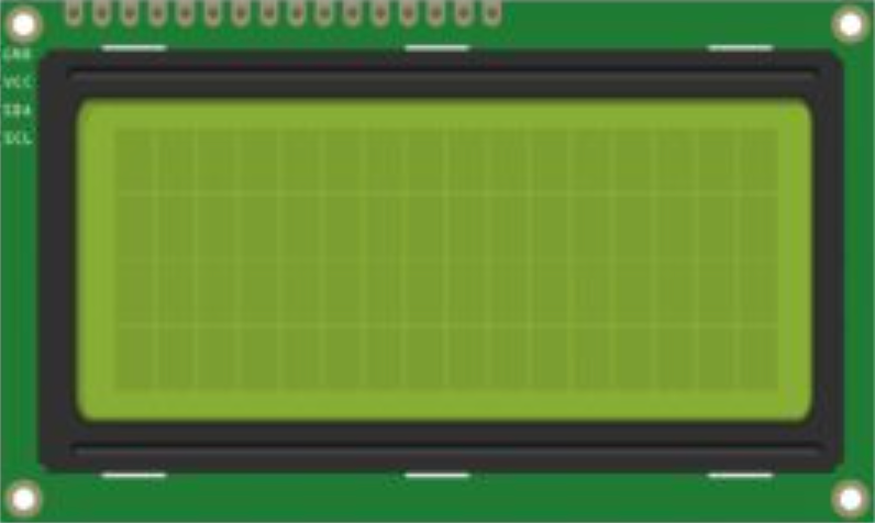
The LCD 20x4 I2C module is a liquid crystal display that provides a 20 characters by 4 lines display with an integrated I2C interface for communication. This module is widely used in various electronic projects and devices, such as DIY electronics, user interfaces, and information displays, due to its ease of use and the ability to display ample information.
Explore Projects Built with Lcd 20x4 i2c

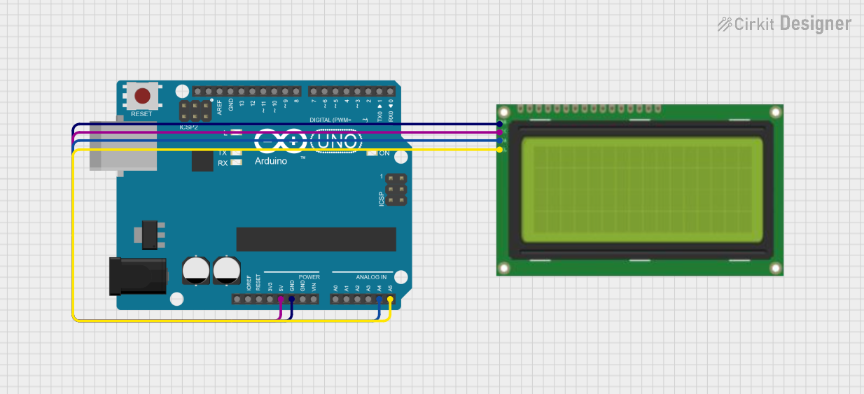
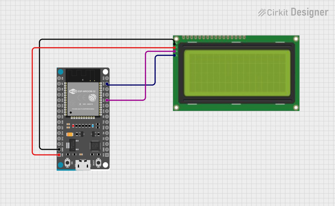
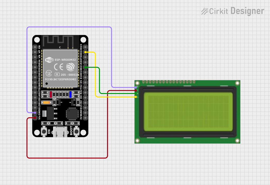
Explore Projects Built with Lcd 20x4 i2c
Common Applications and Use Cases
- User interfaces for embedded systems
- Real-time data output displays
- Menu displays for settings and options
- Debugging tool for displaying system statuses
Technical Specifications
Key Technical Details
- Display: 20 characters by 4 lines
- Character Size: 2.95 x 4.35 mm
- Backlight: LED, Yellow-Green
- I2C Interface: Serial
- Supply Voltage: 5V
- I2C Address: 0x27 (default, can vary)
Pin Configuration and Descriptions
| Pin Number | Pin Name | Description |
|---|---|---|
| 1 | GND | Ground |
| 2 | VCC | Supply Voltage (5V) |
| 3 | SDA | I2C Data Line |
| 4 | SCL | I2C Clock Line |
| 5 | RW | Read/Write Select (typically tied to GND) |
| 6 | RS | Register Select |
| 7-14 | D0-D7 | 8-bit Data Bus (not used in I2C mode) |
| 15 | A | Anode for Backlight LED |
| 16 | K | Cathode for Backlight LED |
Usage Instructions
How to Use the Component in a Circuit
- Connect the GND pin to the ground of the power supply.
- Connect the VCC pin to a 5V power supply.
- Connect the SDA and SCL pins to the I2C data and clock lines, respectively.
- If available, connect the A and K pins to a power source and ground to turn on the backlight.
Important Considerations and Best Practices
- Ensure that pull-up resistors are connected to the SDA and SCL lines if they are not provided on the module.
- Avoid long I2C cable runs to prevent signal degradation.
- Use a level shifter if interfacing with a microcontroller operating at a voltage other than 5V.
Example Code for Arduino UNO
#include <Wire.h>
#include <LiquidCrystal_I2C.h>

// Initialize the library with the I2C address 0x27 for the LCD
LiquidCrystal_I2C lcd(0x27, 20, 4);

void setup() {
  // Initialize the LCD and turn on the backlight
  lcd.init();
  lcd.backlight();

  // Print a message to the LCD
  lcd.setCursor(0, 0); // Set the cursor to the top-left position
  lcd.print("Hello, World!");
  lcd.setCursor(0, 1); // Move to the second line
  lcd.print("LCD 20x4 I2C Module");
}

void loop() {
  // Main loop does nothing in this example
}
Troubleshooting and FAQs
Common Issues Users Might Face
- Display not powering on: Check the connections to VCC and GND, and ensure the power supply is 5V.
- Characters not displaying correctly: Verify that the I2C address is correct and that the SDA and SCL lines are properly connected with pull-up resistors.
- Backlight not working: Ensure that the A and K pins are correctly connected to the power source and ground.
Solutions and Tips for Troubleshooting
- Use an I2C scanner sketch to confirm the I2C address of the LCD module.
- Adjust the contrast potentiometer on the back of the LCD module if characters are faint or too dark.
- Check for soldering issues on the I2C interface module if communication is unreliable.
FAQs
Q: How do I change the I2C address of the module? A: The I2C address can be changed by adjusting the hardware jumpers on the back of the I2C interface module, if available.
Q: Can I use this module with a 3.3V system? A: Yes, but a level shifter is recommended to match the I2C logic levels, and you may need to provide a separate 5V supply for the LCD itself.
Q: How can I clear the display?
A: Use the lcd.clear() function in your code to clear the display and reset the cursor position.
This documentation provides a comprehensive guide to integrating and using the LCD 20x4 I2C module in your projects. For further assistance, consult the datasheet of the specific module or reach out to the community forums for support.