How to Use wa ragud: Examples, Pinouts, and Specs

Introduction
The WA RAGUD, manufactured by SGD with the part ID ARAY KO, is a fictional or non-standard electronic component. While its exact purpose and functionality are undefined, it can serve as a placeholder name in circuit design discussions, educational contexts, or hypothetical scenarios. This documentation provides a general framework for understanding and utilizing such components in theoretical or experimental applications.
Explore Projects Built with wa ragud
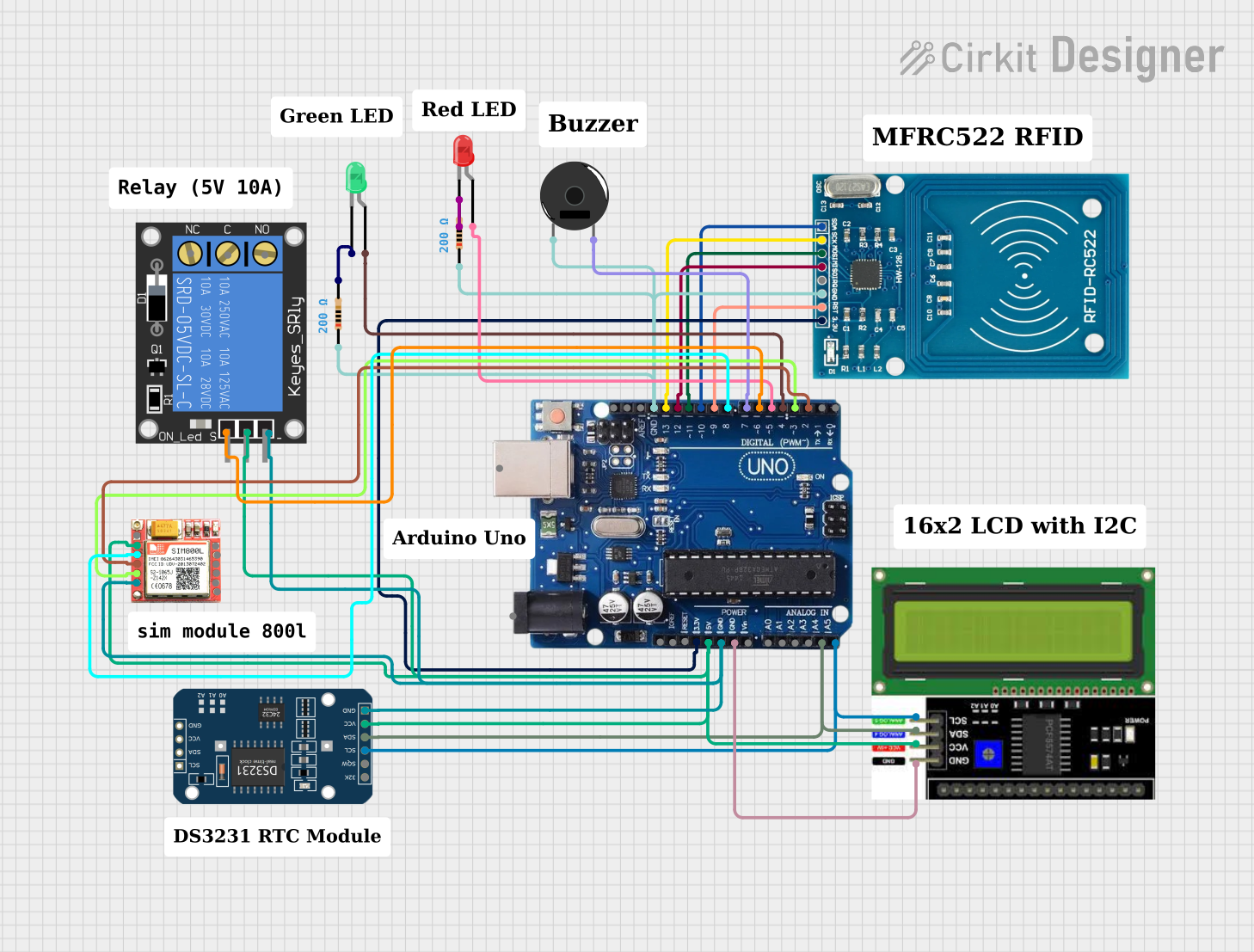
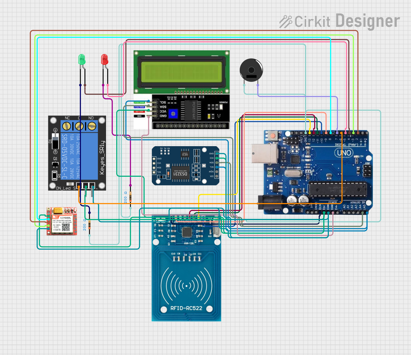
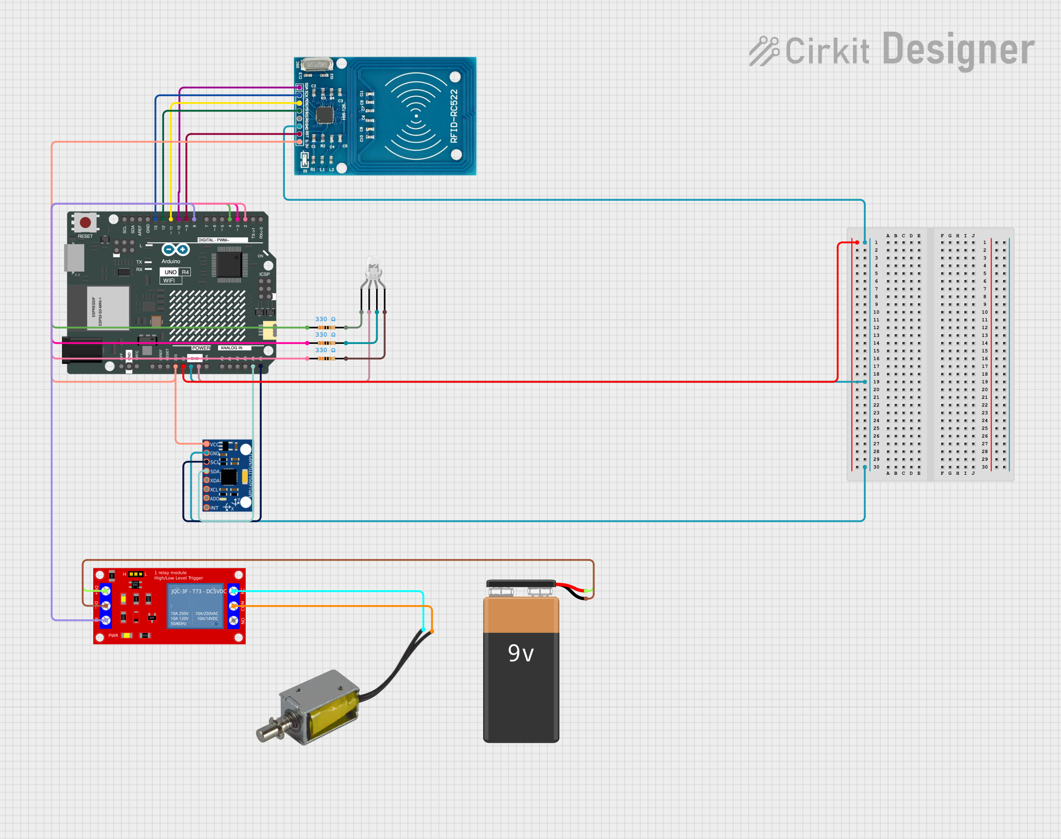
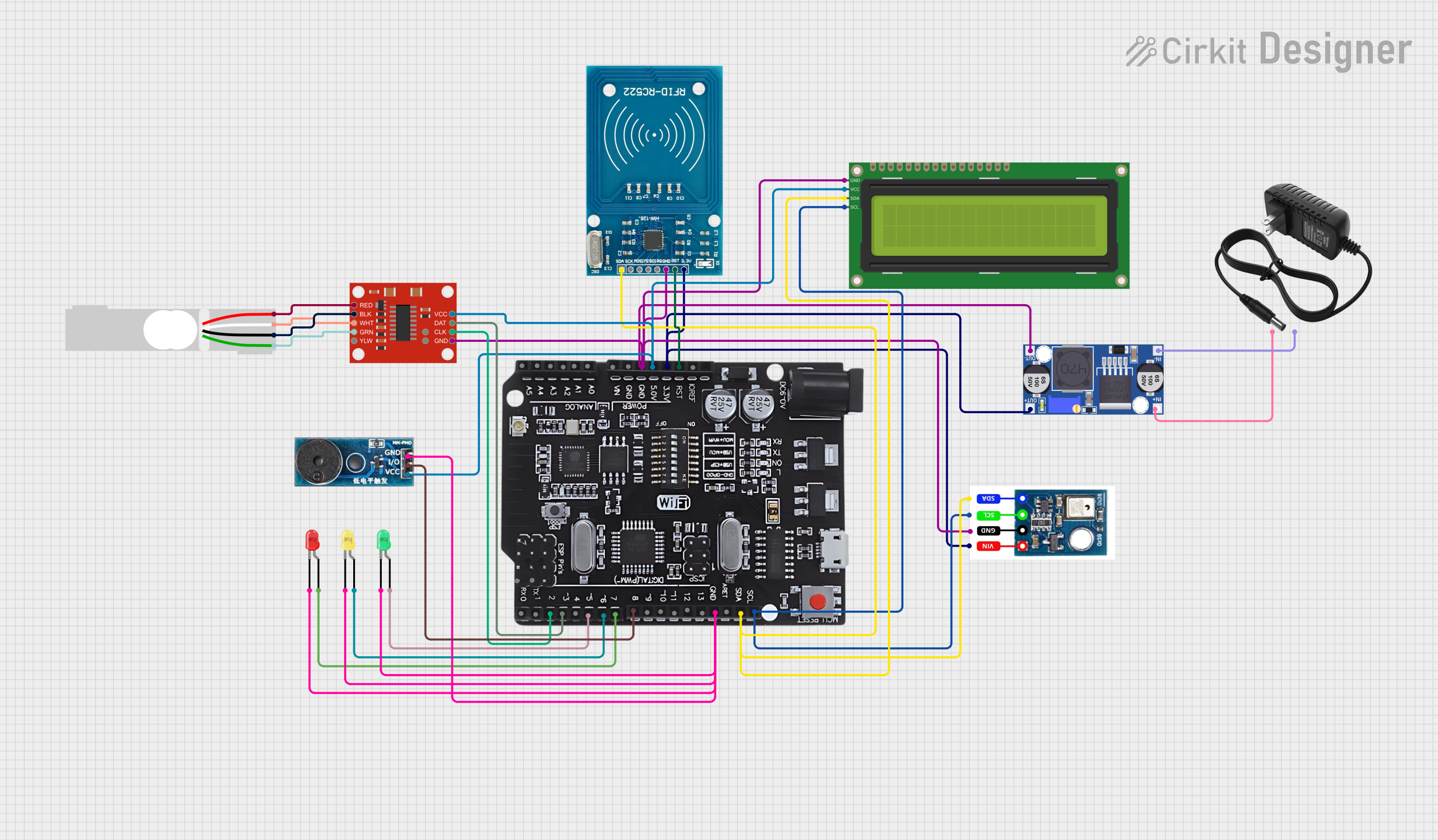
Explore Projects Built with wa ragud
Common Applications and Use Cases
- Placeholder for undefined or experimental components in circuit design.
- Educational tool for teaching circuit design and troubleshooting.
- Hypothetical scenarios in electronics simulations or discussions.
Technical Specifications
As the WA RAGUD is a fictional component, its technical specifications are undefined. However, for the sake of theoretical application, the following generic specifications can be assumed:
| Parameter | Value | Description |
|---|---|---|
| Voltage Range | 0-5V (assumed) | Typical operating voltage range. |
| Current Rating | 10mA (assumed) | Maximum current the component can handle. |
| Power Rating | 50mW (assumed) | Maximum power dissipation. |
| Pin Count | 3 | Number of pins for connection. |
Pin Configuration and Descriptions
| Pin Number | Pin Name | Description |
|---|---|---|
| 1 | VCC | Power supply input (assumed). |
| 2 | GND | Ground connection. |
| 3 | OUT | Output signal or data pin (assumed). |
Usage Instructions
How to Use the Component in a Circuit
- Power Supply: Connect the VCC pin to a suitable power source (e.g., 5V) and the GND pin to the circuit ground.
- Output Connection: Use the OUT pin to interface with other components or microcontrollers.
- Simulation: If using in a simulation, define the component's behavior based on the intended application.
Important Considerations and Best Practices
- Assumptions: Clearly define the component's behavior and specifications before use in a circuit.
- Testing: Use a breadboard or simulation software to test the component's functionality in the circuit.
- Documentation: Maintain detailed notes on how the component is used and its assumed characteristics.
Example Code for Arduino UNO
If the WA RAGUD is assumed to output a digital signal, the following Arduino code demonstrates how to read the signal:
// Define the pin connected to the WA RAGUD's OUT pin
const int waRagudPin = 2;

void setup() {
  // Initialize the serial monitor for debugging
  Serial.begin(9600);

  // Set the WA RAGUD pin as an input
  pinMode(waRagudPin, INPUT);
}

void loop() {
  // Read the signal from the WA RAGUD's OUT pin
  int signal = digitalRead(waRagudPin);

  // Print the signal value to the serial monitor
  Serial.print("WA RAGUD Signal: ");
  Serial.println(signal);

  // Add a small delay to avoid flooding the serial monitor
  delay(500);
}
Note: The above code assumes the WA RAGUD outputs a digital HIGH or LOW signal. Modify the code as needed based on the component's actual or assumed behavior.
Troubleshooting and FAQs
Common Issues Users Might Face
No Output Signal:
- Ensure the VCC and GND pins are correctly connected.
- Verify the assumed behavior of the component matches the circuit design.
Incorrect Signal Readings:
- Check for loose connections or faulty wiring.
- Ensure the Arduino pin configuration matches the circuit.
Component Overheating:
- Verify the power supply voltage and current do not exceed the assumed ratings.
- Use a resistor or other protective components if necessary.
Solutions and Tips for Troubleshooting
- Simulation First: Test the component in simulation software before physical implementation.
- Document Assumptions: Clearly outline the assumed specifications and behavior of the component.
- Consult Experts: If using the component in a hypothetical or educational context, seek guidance from experienced engineers or educators.
This documentation serves as a flexible guide for working with the WA RAGUD in theoretical or experimental scenarios.