Cirkit Designer Logo
Cirkit Designer
Your all-in-one circuit design IDE
Home / 
Component Documentation

How to Use Adafruit FT232H Breakout: Examples, Pinouts, and Specs

Image of Adafruit FT232H Breakout
Cirkit Designer LogoDesign with Adafruit FT232H Breakout in Cirkit Designer

Introduction

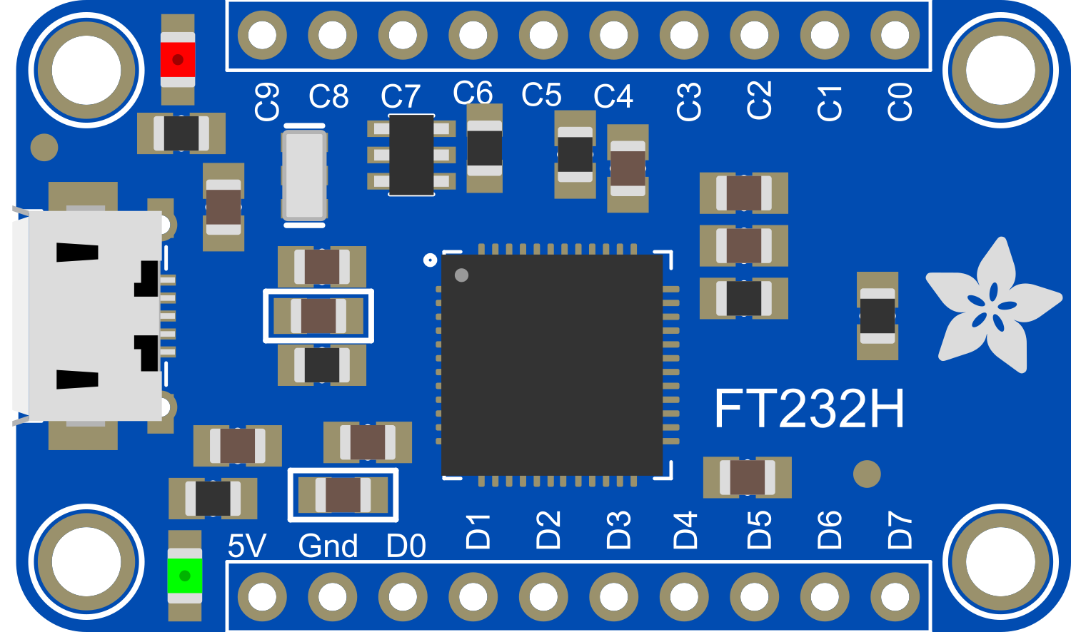
The Adafruit FT232H Breakout is a versatile and powerful USB interface board that provides a bridge between USB and a variety of serial and parallel interfaces. This breakout board is based on the FT232H IC from FTDI and is capable of USB to GPIO, SPI, I2C, and JTAG communication. It is equipped with a USB Type C connector, making it easy to connect to modern computers. The FT232H Breakout is ideal for interfacing with sensors, displays, and a multitude of other devices in a development or prototyping environment.

Explore Projects Built with Adafruit FT232H Breakout

Use Cirkit Designer to design, explore, and prototype these projects online. Some projects support real-time simulation. Click "Open Project" to start designing instantly!
FTDI to UART Adapter with J26 Connector
Image of J26 CLOSEUP: A project utilizing Adafruit FT232H Breakout in a practical application
This circuit connects an FTDI USB-to-serial converter to a standard serial interface via a J26 connector. It facilitates serial communication by linking the ground, transmit, receive, data terminal ready, and request to send signals between the FTDI chip and the J26 connector.
Cirkit Designer LogoOpen Project in Cirkit Designer
ESP8266 WiFi Module Serial Interface with Pushbutton Control
Image of esp01 progrmmer: A project utilizing Adafruit FT232H Breakout in a practical application
This circuit features an ESP8266 ESP-01 WiFi module interfaced with an Adafruit FTDI Friend for serial communication. The ESP8266's TXD and RXD pins are connected to the FTDI's RX and TX pins respectively, allowing for data exchange between the microcontroller and a computer. Additionally, a pushbutton is connected to the ESP8266's reset pin, enabling manual resets of the module.
Cirkit Designer LogoOpen Project in Cirkit Designer
ESP32-Based Vibration Feedback System with Quad Alphanumeric Display and ADXL343 Accelerometer
Image of EC444 - Quest 3: A project utilizing Adafruit FT232H Breakout in a practical application
This circuit features an Adafruit HUZZAH32 ESP32 Feather board as the central microcontroller, which is connected to an Adafruit Quad AlphaNumeric Featherwing display and an Adafruit ADXL343 accelerometer via I2C communication (SCL and SDA lines). The ESP32 controls a vibration motor connected to one of its GPIO pins (A5_IO4) and shares a common power supply (3.3V) and ground (GND) with the other components. The purpose of this circuit is likely to read acceleration data, display information on the alphanumeric display, and provide haptic feedback through the vibration motor.
Cirkit Designer LogoOpen Project in Cirkit Designer
Arduino Mega 2560 Controlled TFT Touchscreen Interface
Image of Tablero Moto: A project utilizing Adafruit FT232H Breakout in a practical application
This circuit connects an Arduino Mega 2560 microcontroller to a 3.5-inch 480x320 TFT LCD display. The Arduino provides power, ground, and digital signals to control the display, including data lines for pixel information and control lines for reset, write, and command/data selection. The embedded code initializes the display and configures the Arduino's pins for communication, likely to create a user interface or visual output for a project.
Cirkit Designer LogoOpen Project in Cirkit Designer

Explore Projects Built with Adafruit FT232H Breakout

Use Cirkit Designer to design, explore, and prototype these projects online. Some projects support real-time simulation. Click "Open Project" to start designing instantly!
Image of J26 CLOSEUP: A project utilizing Adafruit FT232H Breakout in a practical application
FTDI to UART Adapter with J26 Connector
This circuit connects an FTDI USB-to-serial converter to a standard serial interface via a J26 connector. It facilitates serial communication by linking the ground, transmit, receive, data terminal ready, and request to send signals between the FTDI chip and the J26 connector.
Cirkit Designer LogoOpen Project in Cirkit Designer
Image of esp01 progrmmer: A project utilizing Adafruit FT232H Breakout in a practical application
ESP8266 WiFi Module Serial Interface with Pushbutton Control
This circuit features an ESP8266 ESP-01 WiFi module interfaced with an Adafruit FTDI Friend for serial communication. The ESP8266's TXD and RXD pins are connected to the FTDI's RX and TX pins respectively, allowing for data exchange between the microcontroller and a computer. Additionally, a pushbutton is connected to the ESP8266's reset pin, enabling manual resets of the module.
Cirkit Designer LogoOpen Project in Cirkit Designer
Image of EC444 - Quest 3: A project utilizing Adafruit FT232H Breakout in a practical application
ESP32-Based Vibration Feedback System with Quad Alphanumeric Display and ADXL343 Accelerometer
This circuit features an Adafruit HUZZAH32 ESP32 Feather board as the central microcontroller, which is connected to an Adafruit Quad AlphaNumeric Featherwing display and an Adafruit ADXL343 accelerometer via I2C communication (SCL and SDA lines). The ESP32 controls a vibration motor connected to one of its GPIO pins (A5_IO4) and shares a common power supply (3.3V) and ground (GND) with the other components. The purpose of this circuit is likely to read acceleration data, display information on the alphanumeric display, and provide haptic feedback through the vibration motor.
Cirkit Designer LogoOpen Project in Cirkit Designer
Image of Tablero Moto: A project utilizing Adafruit FT232H Breakout in a practical application
Arduino Mega 2560 Controlled TFT Touchscreen Interface
This circuit connects an Arduino Mega 2560 microcontroller to a 3.5-inch 480x320 TFT LCD display. The Arduino provides power, ground, and digital signals to control the display, including data lines for pixel information and control lines for reset, write, and command/data selection. The embedded code initializes the display and configures the Arduino's pins for communication, likely to create a user interface or visual output for a project.
Cirkit Designer LogoOpen Project in Cirkit Designer

Common Applications and Use Cases

  • Interfacing with SPI and I2C devices such as sensors, EEPROMs, and displays.
  • General-purpose GPIO control for home automation or robotics projects.
  • JTAG debugging for microcontrollers and FPGAs.
  • Prototyping USB devices.
  • Bridging USB to serial protocols for communication with microcontrollers.

Technical Specifications

Key Technical Details

  • USB Interface: USB 2.0 Hi-Speed (480 Mb/s)
  • Logic Voltage Levels: 3.3V (5V tolerant inputs)
  • Current Rating: 500mA (USB bus-powered)
  • GPIO Pins: 15, configurable as digital inputs or outputs
  • SPI Ports: 2, with speeds up to 30 MHz
  • I2C Ports: 2, with speeds up to 3.4 MHz
  • JTAG Port: 1, for programming and debugging

Pin Configuration and Descriptions

Pin Number Name Type Description
1 D0 I/O GPIO/SPI/I2C/JTAG Function
2 D1 I/O GPIO/SPI/I2C/JTAG Function
... ... ... ...
15 D14 I/O GPIO/SPI/I2C/JTAG Function

Note: The above table is a simplified representation. Please refer to the official datasheet for complete pin descriptions.

Usage Instructions

How to Use the Component in a Circuit

  1. Powering the Board:

    • Connect the USB Type C cable from the FT232H Breakout to a host computer.
    • Ensure that the drivers for the FT232H are installed on the host computer.
  2. Configuring the Pins:

    • Determine the function for each pin (GPIO, SPI, I2C, or JTAG) based on your application.
    • Configure the pins using the provided Adafruit libraries or FTDI's D2XX drivers.
  3. Connecting to Devices:

    • For SPI/I2C devices, connect the corresponding pins (SCK, MOSI, MISO, SDA, SCL) to the device.
    • For GPIO, connect the desired pins to the inputs/outputs of your circuit.

Important Considerations and Best Practices

  • Always ensure that the connected devices are compatible with the logic voltage levels of the FT232H (3.3V, 5V tolerant).
  • Avoid drawing more than 500mA from the USB port to prevent overloading.
  • Use proper decoupling capacitors close to the power pins of the devices connected to the FT232H.
  • When using JTAG, ensure that the target device's JTAG interface is correctly configured and that the correct pinout is used.

Troubleshooting and FAQs

Common Issues

  • Device Not Recognized: Ensure that the drivers are correctly installed and that the USB cable is functioning.
  • Communication Errors: Check the wiring and pin configuration. Ensure that the baud rate and other communication parameters are correctly set.
  • Insufficient Power: If devices connected to the FT232H are not functioning correctly, verify that they are not drawing more power than the USB port can provide.

Solutions and Tips for Troubleshooting

  • Always start with simple examples and test each function separately to isolate issues.
  • Use LED indicators or a logic analyzer to debug GPIO and communication protocols.
  • Consult the FT232H datasheet and Adafruit's detailed guides for advanced troubleshooting steps.

FAQs

  • Can I use the FT232H Breakout with a 5V system? Yes, the inputs are 5V tolerant, but the logic level for outputs is 3.3V.

  • Do I need to install drivers for the FT232H Breakout? Yes, FTDI drivers are required for the FT232H to be recognized by the host computer.

  • How many devices can I connect to the I2C bus? You can connect multiple devices as long as they have unique addresses and the total power consumption does not exceed the USB port's limit.

Example Code for Arduino UNO

// Example code to communicate with an I2C device using the FT232H Breakout
#include <Wire.h>
#include <Adafruit_FT232H.h>

// Initialize FT232H
Adafruit_FT232H ft232h;

void setup() {
  // Begin I2C
  ft232h.begin_I2C();
}

void loop() {
  // Example I2C communication with a device at address 0x40
  uint8_t i2c_addr = 0x40;
  uint8_t reg_addr = 0x01;
  uint8_t data = 0x00;

  // Write to the I2C device
  ft232h.I2C_Write(i2c_addr, reg_addr, &data, 1);
  
  // Read from the I2C device
  ft232h.I2C_Read(i2c_addr, reg_addr, &data, 1);
  
  // Implement your logic here
  
  delay(1000); // Delay for demonstration purposes
}

Note: The above code is for illustrative purposes and assumes the use of an Adafruit library for the FT232H. Ensure that the library is installed and configured correctly before running the code.

This documentation provides an overview of the Adafruit FT232H Breakout, its technical specifications, usage instructions, troubleshooting tips, and an example code snippet for interfacing with an Arduino UNO. For more detailed information, refer to the official Adafruit FT232H Breakout guide and datasheet.