How to Use AD620 Transmitter High Precision Microvolt/Millivolt Voltage Amplifier: Examples, Pinouts, and Specs
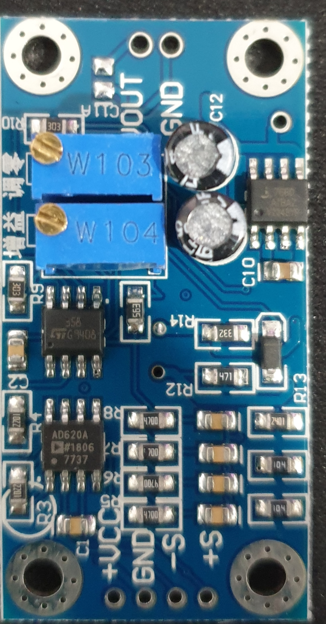
AD620 Transmitter High Precision Microvolt/Millivolt Voltage Amplifier
Manufacturer: YX
Part ID: AD620
1. Introduction
The AD620 is a low-power, high-precision instrumentation amplifier designed to amplify small differential signals in the microvolt to millivolt range. It is widely used in applications requiring accurate signal amplification, such as sensor interfacing, medical instrumentation, and industrial process controls. The AD620 offers excellent performance with low offset voltage, low noise, and high common-mode rejection ratio (CMRR), making it ideal for precision measurement systems.
Common Applications:
- Sensor Signal Amplification: Thermocouples, strain gauges, and pressure sensors.
- Medical Instrumentation: ECG, EEG, and other bio-signal amplifications.
- Data Acquisition Systems: High-accuracy signal conditioning for ADCs.
- Industrial Automation: Process control and monitoring.
2. Technical Specifications
The following table outlines the key technical specifications of the AD620:
| Parameter | Value | Description |
|---|---|---|
| Supply Voltage (VCC) | ±2.3V to ±18V | Operates on dual or single supply. |
| Input Offset Voltage | 50 µV (typical) | Ensures high precision for small signal amplification. |
| Input Bias Current | 1.0 nA (typical) | Low input bias current for high-impedance sources. |
| Gain Range | 1 to 10,000 | Adjustable via an external resistor. |
| Bandwidth | 120 kHz (G = 1) | Wide bandwidth for high-speed applications. |
| Common-Mode Rejection Ratio (CMRR) | 120 dB (typical) | High rejection of common-mode signals for accurate differential measurements. |
| Power Consumption | 1.3 mA (typical) | Low power consumption for battery-powered systems. |
| Package Type | DIP-8, SOIC-8 | Available in standard IC packages for easy integration. |
Pin Configuration and Descriptions
The AD620 is an 8-pin IC. The pinout and descriptions are as follows:
| Pin Number | Pin Name | Description |
|---|---|---|
| 1 | Ref | Reference voltage input. Sets the output voltage reference level. |
| 2 | -In | Inverting input for the differential signal. |
| 3 | +In | Non-inverting input for the differential signal. |
| 4 | -VCC | Negative power supply. |
| 5 | RG | Gain resistor connection. Determines the amplifier gain. |
| 6 | Output | Amplified output signal. |
| 7 | +VCC | Positive power supply. |
| 8 | RG | Gain resistor connection. Determines the amplifier gain. |
3. Usage Instructions
Basic Circuit Configuration
To use the AD620, connect the differential signal to the +In and -In pins. The gain is set by connecting a resistor (RG) between the RG pins (pins 5 and 8). The gain is calculated using the formula:
[ G = 1 + \frac{49.4 , k\Omega}{R_G} ]
Where:
- ( G ) is the gain of the amplifier.
- ( R_G ) is the external resistor in ohms.
If no resistor is connected, the gain defaults to 1.
Example Circuit
Below is an example of a basic configuration for amplifying a thermocouple signal:
- +In (Pin 3): Connect to the positive terminal of the thermocouple.
- -In (Pin 2): Connect to the negative terminal of the thermocouple.
- RG (Pins 5 and 8): Connect a resistor to set the desired gain.
- Ref (Pin 1): Connect to ground or a reference voltage.
- Output (Pin 6): Connect to the input of an ADC or other processing circuit.
- +VCC (Pin 7): Connect to a positive power supply (e.g., +5V).
- -VCC (Pin 4): Connect to a negative power supply (e.g., -5V) or ground for single-supply operation.
Important Considerations:
- Power Supply Decoupling: Use 0.1 µF and 10 µF capacitors close to the power supply pins to reduce noise.
- Input Impedance: Ensure the source impedance is low to avoid signal attenuation.
- Gain Resistor Selection: Use precision resistors for accurate gain settings.
- Common-Mode Voltage Range: Ensure the input signal stays within the specified common-mode voltage range.
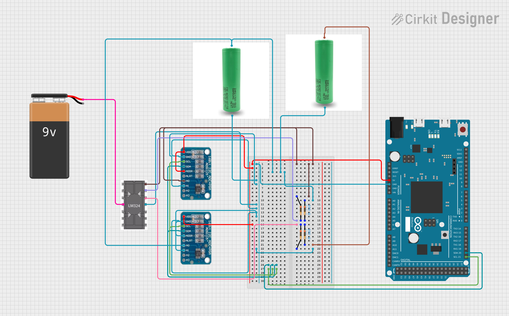
4. Example Code for Arduino UNO
The AD620 can be interfaced with an Arduino UNO for sensor signal amplification. Below is an example code for reading an amplified signal from the AD620:
// Example: Reading AD620 Amplified Signal with Arduino UNO
// This code reads the amplified signal from the AD620 and displays it via Serial Monitor.

const int analogPin = A0; // Connect AD620 output to Arduino A0 pin

void setup() {
  Serial.begin(9600); // Initialize serial communication at 9600 baud
}

void loop() {
  int sensorValue = analogRead(analogPin); // Read the analog value (0-1023)

  // Convert the analog value to voltage (assuming 5V reference)
  float voltage = sensorValue * (5.0 / 1023.0);

  // Print the voltage to the Serial Monitor
  Serial.print("Amplified Voltage: ");
  Serial.print(voltage, 3); // Print voltage with 3 decimal places
  Serial.println(" V");

  delay(500); // Wait for 500ms before the next reading
}
Notes:
- Connect the AD620 output (Pin 6) to the Arduino's analog input pin (e.g., A0).
- Ensure the Arduino and AD620 share a common ground.
- Adjust the gain resistor (RG) to amplify the signal within the Arduino's input range (0-5V).
5. Troubleshooting and FAQs
Common Issues and Solutions
| Issue | Possible Cause | Solution |
|---|---|---|
| No output signal | Incorrect power supply connections | Verify the power supply connections and voltage levels. |
| Output signal is noisy | Insufficient power supply decoupling | Add decoupling capacitors (0.1 µF and 10 µF) near the power supply pins. |
| Output signal is saturated | Input signal exceeds common-mode range | Ensure the input signal is within the specified common-mode voltage range. |
| Incorrect gain | Wrong or unstable gain resistor (RG) | Use a precision resistor and verify the gain calculation. |
| Output signal is distorted | High source impedance | Use a buffer or reduce the source impedance. |
Frequently Asked Questions
Can the AD620 operate with a single power supply?
Yes, the AD620 can operate with a single supply. Connect -VCC (Pin 4) to ground and +VCC (Pin 7) to a positive voltage (e.g., +5V).What is the maximum gain I can achieve?
The maximum gain is 10,000, but ensure the input signal and power supply are configured to avoid saturation.How do I reduce noise in my circuit?
Use proper grounding, shielded cables, and decoupling capacitors to minimize noise.Can I use the AD620 for AC signals?
Yes, the AD620 can amplify AC signals. Use coupling capacitors to block DC offsets if necessary.
This documentation provides a comprehensive guide to using the AD620 High Precision Voltage Amplifier. For further assistance, refer to the manufacturer's datasheet or contact technical support.
Explore Projects Built with AD620 Transmitter High Precision Microvolt/Millivolt Voltage Amplifier


Explore Projects Built with AD620 Transmitter High Precision Microvolt/Millivolt Voltage Amplifier