
How to Use ESP32 Devkit V1: Examples, Pinouts, and Specs
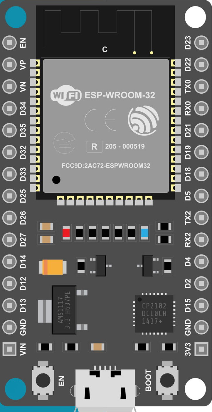
 Design with ESP32 Devkit V1 in Cirkit Designer
Introduction
The ESP32 Devkit V1 is a versatile microcontroller development board based on the ESP32 chip. It features built-in Wi-Fi and Bluetooth capabilities, making it an excellent choice for Internet of Things (IoT) applications, smart devices, and rapid prototyping. With its dual-core processor, low power consumption, and extensive GPIO pins, the ESP32 Devkit V1 is suitable for a wide range of projects, from home automation to wearable devices.
Explore Projects Built with ESP32 Devkit V1
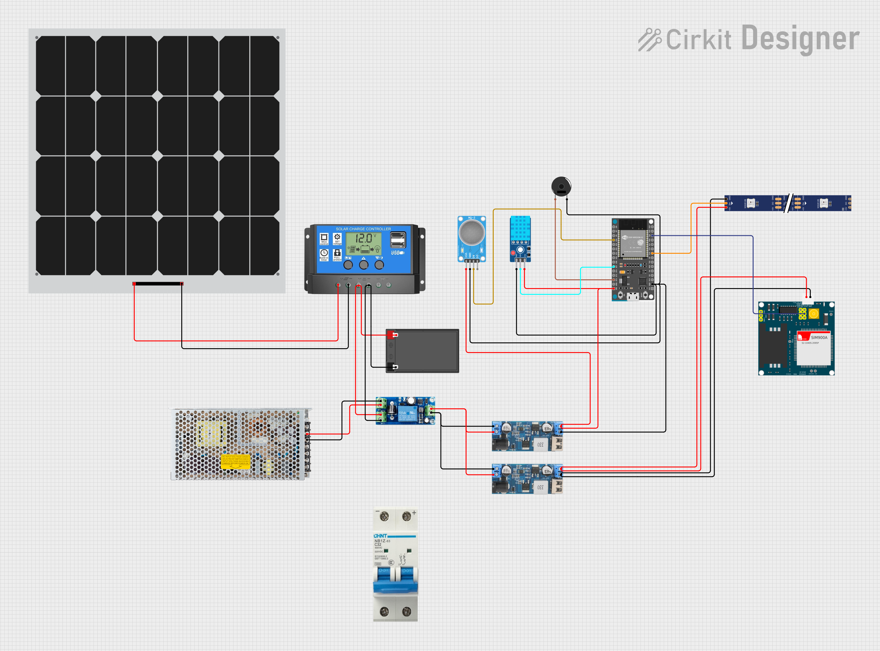 Open Project in Cirkit Designer
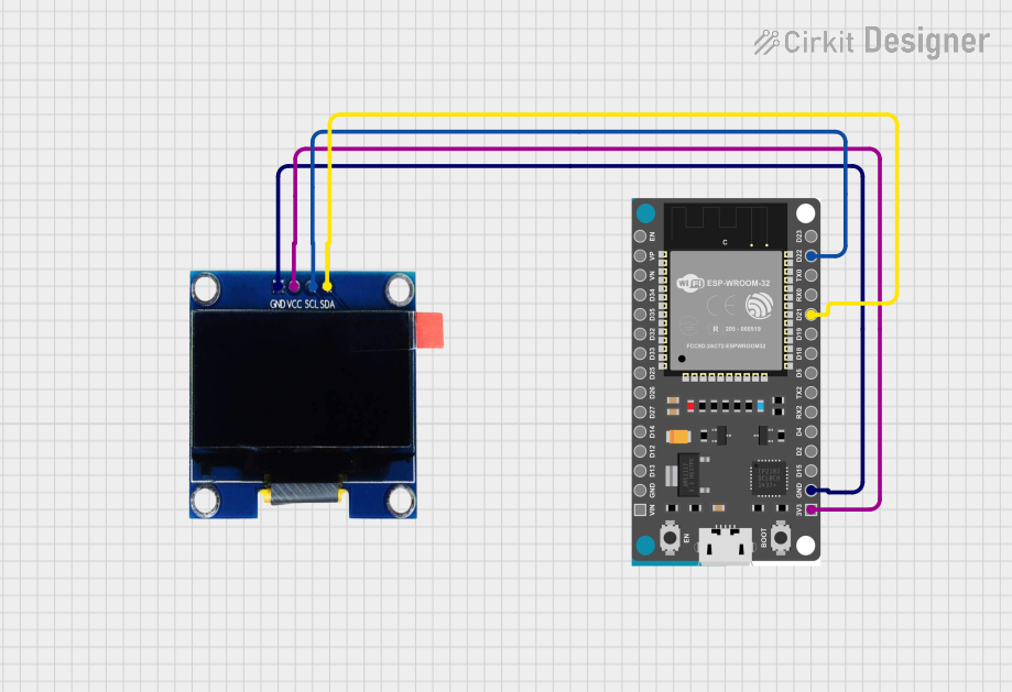 Open Project in Cirkit Designer
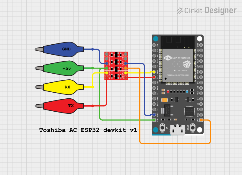 Open Project in Cirkit Designer
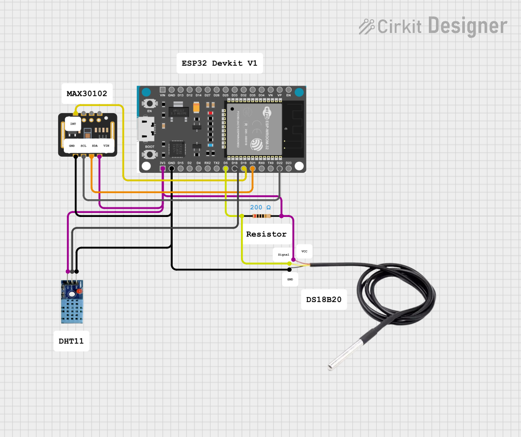 Open Project in Cirkit Designer
Explore Projects Built with ESP32 Devkit V1
Open Project in Cirkit DesignerOpen Project in Cirkit DesignerOpen Project in Cirkit DesignerOpen Project in Cirkit DesignerCommon Applications and Use Cases
- IoT devices and smart home systems
- Wireless sensor networks
- Wearable technology
- Robotics and automation
- Data logging and remote monitoring
- Prototyping for Bluetooth and Wi-Fi-enabled devices
Technical Specifications
The ESP32 Devkit V1 is equipped with the following key features and specifications:
| Specification | Details |
|---|---|
| Microcontroller | ESP32-D0WDQ6 chip with dual-core Xtensa® 32-bit LX6 processor |
| Clock Speed | Up to 240 MHz |
| Flash Memory | 4 MB (varies by model) |
| SRAM | 520 KB |
| Wireless Connectivity | Wi-Fi 802.11 b/g/n, Bluetooth v4.2 + BLE |
| Operating Voltage | 3.3V |
| Input Voltage (VIN) | 5V (via USB or external power supply) |
| GPIO Pins | 30 (varies slightly by board version) |
| ADC Channels | 18 (12-bit resolution) |
| DAC Channels | 2 |
| Communication Interfaces | UART, SPI, I2C, I2S, CAN, PWM |
| Power Consumption | Ultra-low power consumption with multiple power modes |
| Dimensions | Approx. 54 mm x 27 mm |
Pin Configuration and Descriptions
The ESP32 Devkit V1 has a total of 30 pins, with the following key pin assignments:
| Pin | Name | Description |
|---|---|---|
| 1 | VIN | Input voltage (5V) for powering the board |
| 2 | GND | Ground pin |
| 3 | 3V3 | 3.3V output from the onboard voltage regulator |
| 4-21 | GPIO0-GPIO39 | General-purpose input/output pins (various functions: ADC, DAC, PWM, etc.) |
| 22 | EN | Enable pin (active high, used to reset the chip) |
| 23 | TXD0 | UART0 Transmit pin |
| 24 | RXD0 | UART0 Receive pin |
| 25 | SCL | I2C Clock line |
| 26 | SDA | I2C Data line |
| 27 | BOOT | Boot mode selection pin (used for flashing firmware) |
Note: Some GPIO pins have specific functions or limitations. Refer to the ESP32 datasheet for detailed pin capabilities.
Usage Instructions
How to Use the ESP32 Devkit V1 in a Circuit
Powering the Board:
- Connect the board to your computer via a micro-USB cable for power and programming.
- Alternatively, supply 5V to the VIN pin and connect GND to the ground of your power source.
Programming the Board:
- Install the Arduino IDE and add the ESP32 board support package.
- Select "ESP32 Dev Module" from the Tools > Board menu.
- Connect the board to your computer and select the appropriate COM port.
Connecting Peripherals:
- Use the GPIO pins to connect sensors, actuators, or other peripherals.
- Ensure that the voltage levels of connected devices are compatible with the ESP32 (3.3V logic).
Uploading Code:
- Write your code in the Arduino IDE or another compatible environment.
- Click the "Upload" button to flash the code to the ESP32.
- If the upload fails, press and hold the BOOT button while uploading.
Example Code: Blinking an LED
The following example demonstrates how to blink an LED connected to GPIO2:
// Define the GPIO pin where the LED is connected
const int ledPin = 2;

void setup() {
  // Set the LED pin as an output
  pinMode(ledPin, OUTPUT);
}

void loop() {
  // Turn the LED on
  digitalWrite(ledPin, HIGH);
  delay(1000); // Wait for 1 second

  // Turn the LED off
  digitalWrite(ledPin, LOW);
  delay(1000); // Wait for 1 second
}
Important Considerations and Best Practices
- Voltage Levels: The ESP32 operates at 3.3V logic. Avoid connecting 5V devices directly to GPIO pins without level shifters.
- Power Supply: Ensure a stable power supply, especially when using Wi-Fi or Bluetooth, as these features can cause power spikes.
- Boot Mode: If the board does not boot properly, check the state of the BOOT and EN pins.
- GPIO Limitations: Some GPIO pins are reserved for specific functions or have pull-up/pull-down resistors. Refer to the ESP32 datasheet for details.
Troubleshooting and FAQs
Common Issues and Solutions
Problem: The board is not detected by the computer.
Solution:- Ensure the USB cable is functional and supports data transfer.
- Install the correct USB-to-serial driver (e.g., CP2102 or CH340, depending on your board).
Problem: Code upload fails with a timeout error.
Solution:- Press and hold the BOOT button while uploading the code.
- Check that the correct COM port and board type are selected in the Arduino IDE.
Problem: Wi-Fi connection is unstable.
Solution:- Ensure a strong Wi-Fi signal and minimize interference.
- Use a stable power supply to avoid voltage drops during Wi-Fi operation.
Problem: GPIO pins are not functioning as expected.
Solution:- Verify that the pins are not reserved for specific functions (e.g., GPIO0, GPIO2).
- Check for conflicts with other peripherals or incorrect pinMode settings.
FAQs
Q: Can I power the ESP32 Devkit V1 with a battery?
A: Yes, you can use a 3.7V LiPo battery connected to the 3V3 pin or a 5V source connected to the VIN pin.Q: How do I reset the ESP32?
A: Press the EN button to reset the board.Q: Can I use the ESP32 with MicroPython?
A: Yes, the ESP32 supports MicroPython. Flash the MicroPython firmware to the board and use a compatible IDE like Thonny.Q: What is the maximum current draw of the ESP32?
A: The ESP32 can draw up to 500 mA during peak operation (e.g., Wi-Fi transmission). Ensure your power supply can handle this.
This concludes the documentation for the ESP32 Devkit V1.