
How to Use ESP8285 ESP-M3: Examples, Pinouts, and Specs
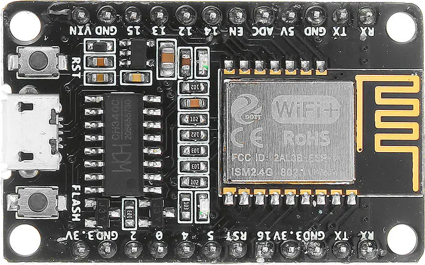
 Design with ESP8285 ESP-M3 in Cirkit Designer
Introduction
The ESP8285 ESP-M3 is a highly integrated Wi-Fi SoC (System on Chip) developed by Espressif Systems. It is a compact version of the popular ESP8266, with the added advantage of having 1MB of internal flash memory. This makes the ESP-M3 suitable for space-constrained Internet of Things (IoT) projects. It is commonly used in smart home devices, wireless sensors, and other IoT applications due to its small form factor and powerful features.
Explore Projects Built with ESP8285 ESP-M3
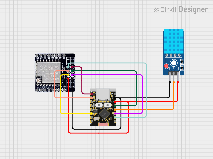
 Open Project in Cirkit Designer
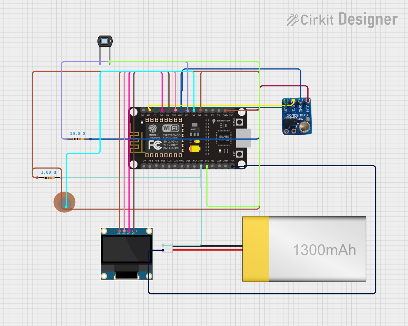
 Open Project in Cirkit Designer
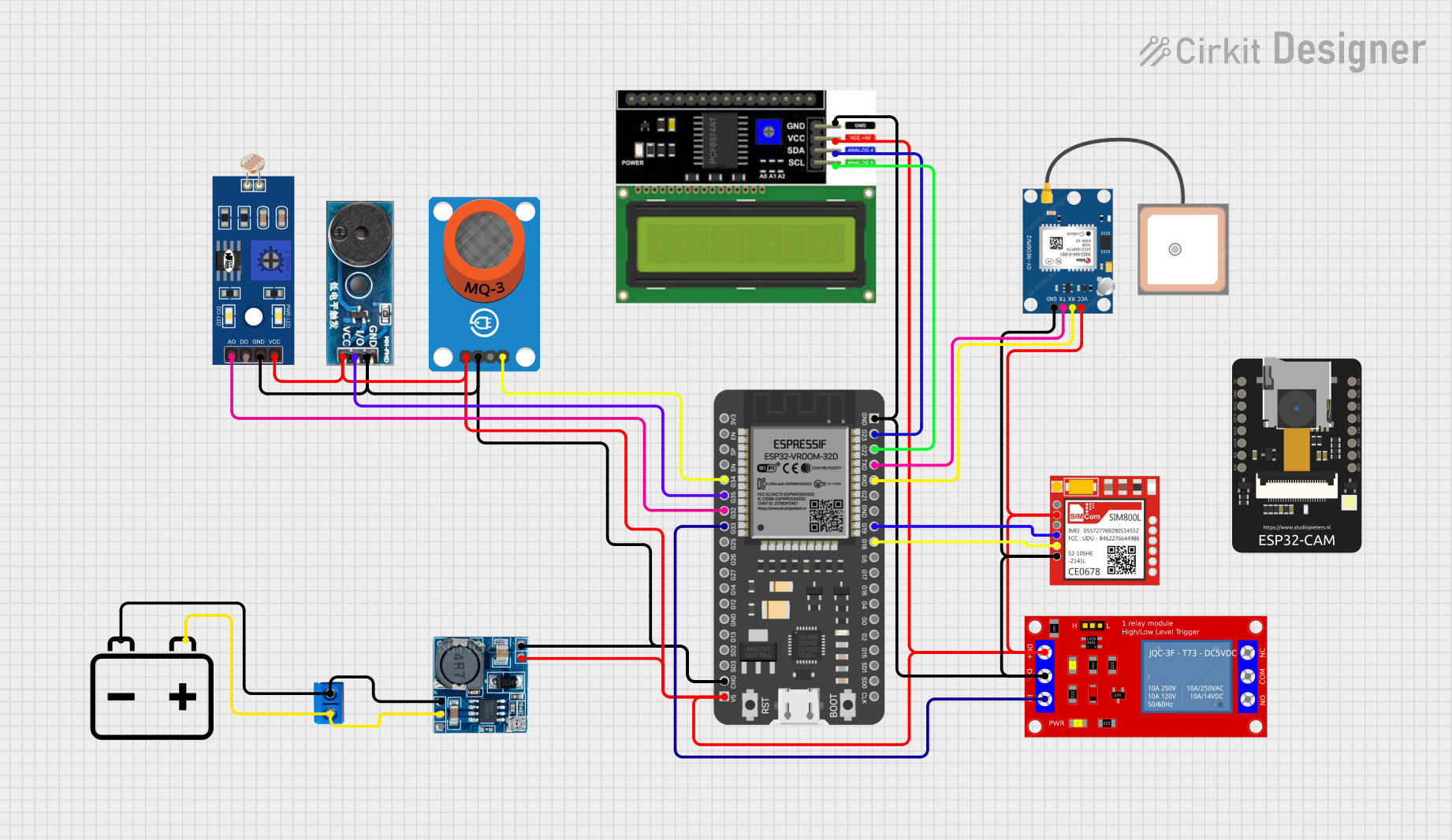
 Open Project in Cirkit Designer
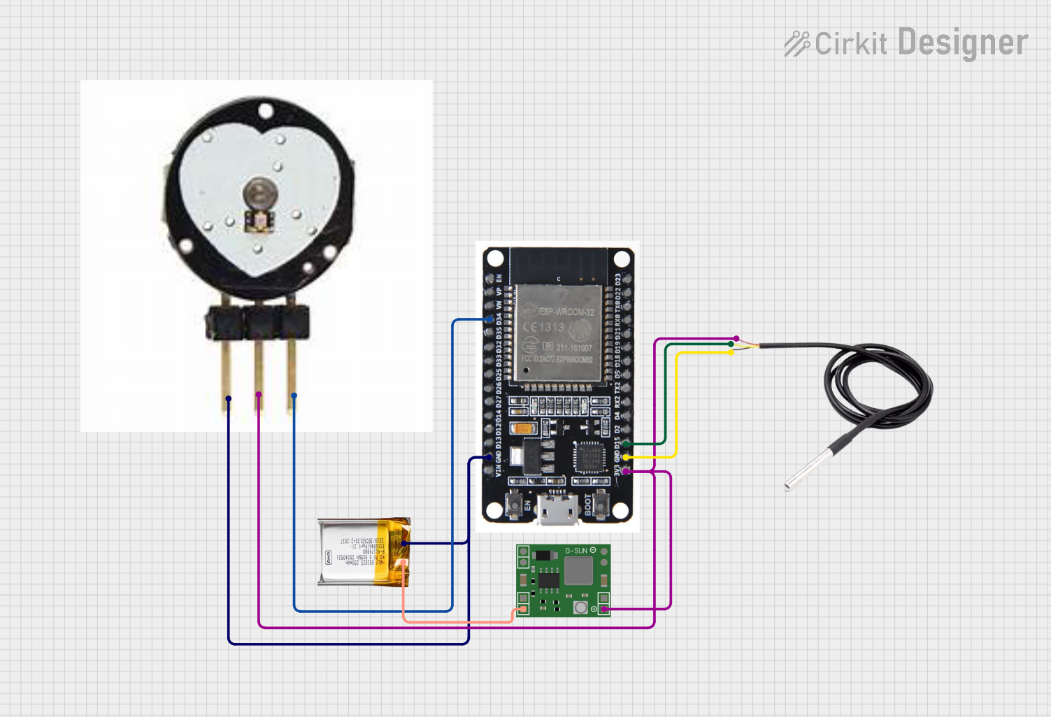
 Open Project in Cirkit Designer
Explore Projects Built with ESP8285 ESP-M3

 Open Project in Cirkit Designer
 Open Project in Cirkit Designer
 Open Project in Cirkit Designer
 Open Project in Cirkit Designer
Technical Specifications
Key Technical Details
- Wi-Fi Standards: 802.11 b/g/n
- Frequency Range: 2.4 GHz - 2.5 GHz
- Operating Voltage: 3.0V to 3.6V
- Recommended Operating Voltage: 3.3V
- Peak Current Consumption: Approx. 170 mA (during Tx)
- Sleep Current Consumption: < 10 µA
- CPU: Tensilica L106 32-bit microcontroller
- CPU Clock Speed: 80 MHz (can be overclocked to 160 MHz)
- Flash Memory: 1MB integrated
- GPIO Pins: 17 (multiplexed with other functions)
- ADC: 10-bit precision
- UART: 2 (one for programming and AT commands, one for user applications)
- SPI: Yes
- I2C: Yes
- PWM: Yes, on selected pins
Pin Configuration and Descriptions
| Pin Number | Name | Function |
|---|---|---|
| 1 | VCC | Power supply (3.3V) |
| 2 | GND | Ground |
| 3 | TX | UART Transmit |
| 4 | RX | UART Receive |
| 5 | GPIO0 | General Purpose I/O and Flash Programming |
| 6 | RST | Reset Pin |
| 7 | CH_PD | Chip Power-Down Pin |
| 8 | GPIO2 | General Purpose I/O |
| 9 | GPIO15 | General Purpose I/O |
Usage Instructions
Integrating ESP-M3 into a Circuit
Power Supply: Connect the VCC pin to a stable 3.3V power source and GND to the ground. Do not exceed the recommended operating voltage.
Programming: To program the ESP-M3, connect the TX and RX pins to a USB-to-serial adapter. GPIO0 must be grounded during power-up to enter flash mode.
Reset and Boot: Connect the RST pin to a push-button for manual resets. CH_PD must be pulled high (connected to VCC) for normal operation. GPIO15 should be pulled low (connected to GND) for the module to boot from the internal flash.
GPIO Usage: The GPIO pins can be used for input or output functions. Be aware of the boot functions of certain pins (e.g., GPIO0, GPIO2, and GPIO15) and avoid using them in a way that might interfere with the boot process.
Antenna: The ESP-M3 has a built-in PCB antenna. Ensure that the antenna area is not obstructed by metal parts for optimal wireless performance.
Best Practices
- Use a 3.3V voltage regulator with sufficient current capability to ensure a stable power supply.
- Add decoupling capacitors close to the VCC and GND pins to filter out noise.
- Avoid long wires for the UART communication to prevent signal degradation.
- Implement proper ESD protection, especially when handling the module in dry environments.
Example Code for Arduino UNO
#include <ESP8266WiFi.h>

// Replace with your network credentials
const char* ssid = "yourSSID";
const char* password = "yourPASSWORD";

void setup() {
  Serial.begin(115200); // Start the Serial communication
  WiFi.begin(ssid, password); // Connect to the network

  while (WiFi.status() != WL_CONNECTED) { // Wait for the Wi-Fi to connect
    delay(500);
    Serial.print(".");
  }

  Serial.println("");
  Serial.println("WiFi connected");
  Serial.println("IP address: ");
  Serial.println(WiFi.localIP()); // Print the local IP address
}

void loop() {
  // Your code here
}
Ensure that the ESP-M3 module is correctly interfaced with the Arduino UNO for serial communication and that the ESP-M3 is in the correct mode for receiving the program.
Troubleshooting and FAQs
Common Issues
- Module not booting: Check the power supply and the status of GPIO0, GPIO2, and GPIO15 during boot.
- Cannot upload firmware: Ensure GPIO0 is grounded when initiating a flash operation.
- Wi-Fi not connecting: Verify the SSID and password, and ensure the antenna is not obstructed.
Solutions and Tips
- If the module is not responding, perform a hard reset by momentarily connecting the RST pin to GND.
- For issues with serial communication, check the baud rate and the integrity of the TX/RX connection.
- Use external antennas for applications requiring extended range, ensuring you have the variant of the ESP-M3 with an antenna connector.
FAQs
Q: Can the ESP-M3 be used with battery power? A: Yes, but ensure the battery can provide a stable 3.3V and handle the peak current requirements.
Q: Is the ESP-M3 compatible with the Arduino IDE? A: Yes, with the proper board manager installed, you can program the ESP-M3 using the Arduino IDE.
Q: How do I reduce power consumption for battery-powered projects? A: Utilize deep sleep modes and minimize active duty cycles to extend battery life.
For further assistance, consult the Espressif Systems forums and the ESP-M3 community for additional support and resources.