How to Use V_REG_TPS61040: Examples, Pinouts, and Specs
Introduction
The V_REG_TPS61040 is a high-frequency, boost-converter voltage regulator IC designed by Texas Instruments. This component is particularly useful in applications requiring a regulated output voltage from a lower input voltage source. It is capable of stepping up voltages, making it ideal for powering devices that require a higher voltage than what is available from the input source. Common applications include powering OLED displays, CCD sensors, white LED drivers, and portable battery-powered devices.
Explore Projects Built with V_REG_TPS61040

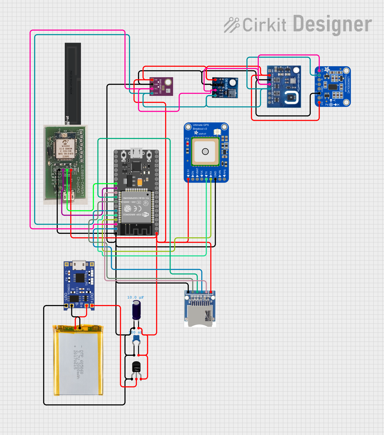
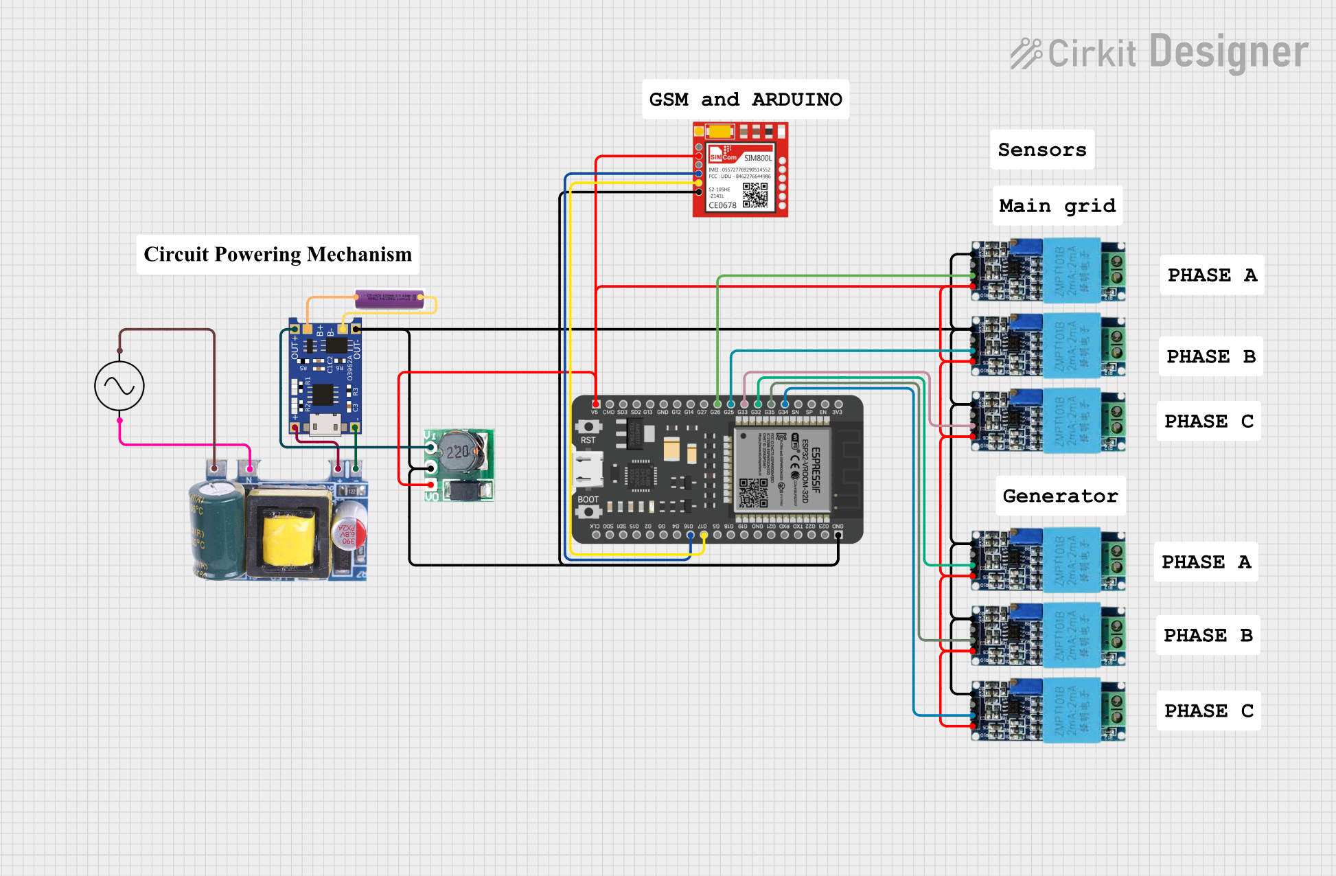

Explore Projects Built with V_REG_TPS61040
Technical Specifications
Key Technical Details
- Input Voltage Range: 1.8 V to 6.0 V
- Output Voltage Range: Adjustable from 1.8 V to 28 V
- Switch Current Limit: Typically 400 mA
- Quiescent Current: Typically 150 µA
- Switching Frequency: Up to 1.2 MHz
- Efficiency: Up to 90%
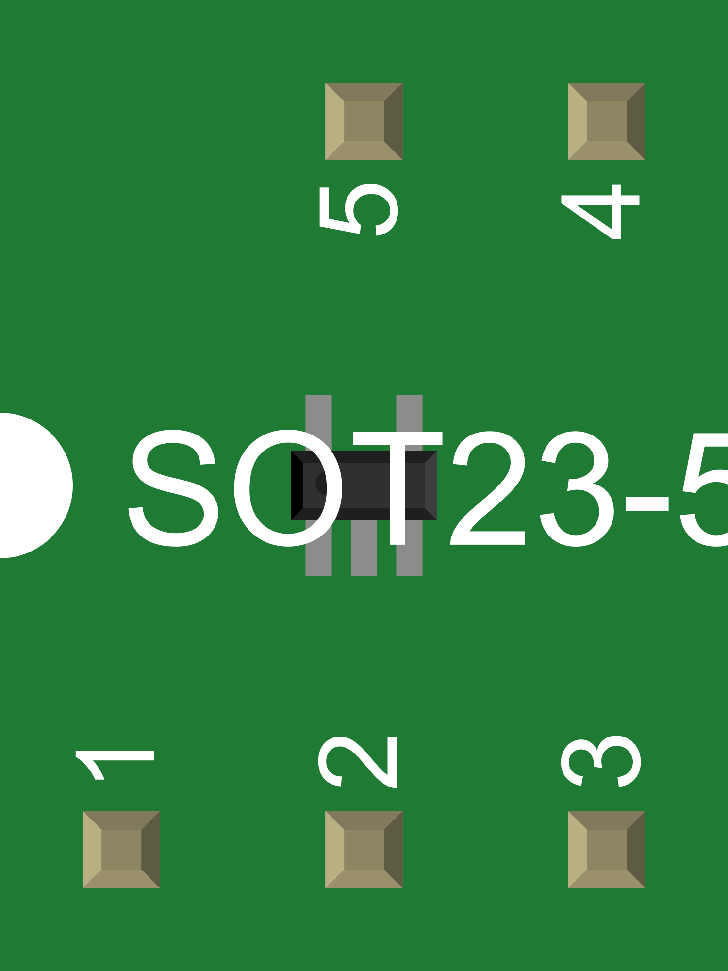
- Package: SOT-23-5
Pin Configuration and Descriptions
| Pin Number | Name | Description |
|---|---|---|
| 1 | VIN | Input voltage. Connect to the source of the unregulated voltage. |
| 2 | GND | Ground. Connect to the system ground. |
| 3 | SW | Switch pin. Connects to the inductor and diode for the boost converter. |
| 4 | FB | Feedback pin. Connects to the voltage divider for output voltage regulation. |
| 5 | EN | Enable pin. A logic high enables the IC, while a logic low disables it. |
Usage Instructions
How to Use the Component in a Circuit
- Input Supply: Connect a filtered and decoupled input voltage source to the VIN pin.
- Ground Connection: Connect the GND pin to the system ground.
- Output Voltage Setting: Set the desired output voltage by choosing appropriate resistor values for the voltage divider connected to the FB pin.
- Inductor Selection: Choose an inductor that can handle the peak switch current and has a low DC resistance.
- Diode Selection: Select a Schottky diode with a low forward voltage drop and a reverse voltage rating higher than the maximum output voltage.
- Output Capacitor: Connect an output capacitor to stabilize the output voltage and reduce voltage ripple.
- Enable Pin: Control the operation of the IC using the EN pin. Apply a logic high to enable the IC.
Important Considerations and Best Practices
- Ensure that the input voltage does not exceed the maximum rating of 6.0 V.
- The output voltage should be set carefully to avoid exceeding the maximum rating of 28 V.
- Use ceramic capacitors for input and output decoupling to minimize noise and voltage ripple.
- Place the IC close to the power source and load to minimize losses and improve efficiency.
- Provide adequate thermal management, as the IC may generate heat during operation.
Troubleshooting and FAQs
Common Issues
- Output Voltage Too Low or High: Check the feedback resistor values and ensure they are within tolerance.
- IC Overheating: Ensure the inductor and diode are correctly rated and that there is sufficient thermal management.
- Output Voltage Unstable: Verify the output capacitor's value and ESR rating are suitable for the application.
Solutions and Tips
- Incorrect Output Voltage: Recalculate and adjust the feedback resistor values.
- Thermal Issues: Improve heat dissipation with a better PCB layout or additional heat sinking.
- Voltage Instability: Increase the output capacitor value or use a capacitor with a lower ESR.
FAQs
Q: Can the V_REG_TPS61040 be used to step down voltage? A: No, it is a boost converter and is designed to step up voltage only.
Q: What is the maximum output current of the V_REG_TPS61040? A: The maximum output current depends on the input voltage, inductor size, and thermal conditions but is typically limited by the 400 mA switch current limit.
Q: How do I enable the V_REG_TPS61040? A: Apply a logic high signal to the EN pin to enable the IC.
Example Code for Arduino UNO
// Example code to enable the V_REG_TPS61040 using an Arduino UNO

const int enablePin = 2; // Connect to the EN pin of the V_REG_TPS61040

void setup() {
  pinMode(enablePin, OUTPUT); // Set the enable pin as an output
}

void loop() {
  digitalWrite(enablePin, HIGH); // Enable the V_REG_TPS61040
  delay(1000); // Wait for 1 second
  digitalWrite(enablePin, LOW); // Disable the V_REG_TPS61040
  delay(1000); // Wait for 1 second
}
This example demonstrates how to toggle the enable pin of the V_REG_TPS61040 to turn the voltage regulator on and off using an Arduino UNO. The enable pin is connected to digital pin 2 on the Arduino. The digitalWrite function is used to set the enable pin high or low, thus controlling the state of the V_REG_TPS61040.