
How to Use HALL-EFFECT: Examples, Pinouts, and Specs
 Design with HALL-EFFECT in Cirkit Designer
Introduction
A Hall-effect sensor detects the presence and strength of a magnetic field, producing a voltage output proportional to the field strength. This non-contact sensing technology is widely used in various applications due to its reliability and precision.
Explore Projects Built with HALL-EFFECT
 Open Project in Cirkit Designer
 Open Project in Cirkit Designer
 Open Project in Cirkit Designer
 Open Project in Cirkit Designer
Explore Projects Built with HALL-EFFECT
Open Project in Cirkit DesignerOpen Project in Cirkit DesignerOpen Project in Cirkit DesignerOpen Project in Cirkit DesignerCommon Applications and Use Cases
- Position Sensing: Detecting the position of objects in automotive and industrial systems.
- Speed Detection: Measuring rotational speed in motors, fans, and wheels.
- Current Sensing: Monitoring current flow in power systems and circuits.
- Proximity Sensing: Detecting the presence of magnetic objects in security systems or consumer electronics.
Technical Specifications
Below are the general technical specifications for a typical Hall-effect sensor. Note that specific models may vary slightly.
| Parameter | Value |
|---|---|
| Operating Voltage (Vcc) | 3.3V to 24V |
| Output Voltage Range | 0V to Vcc |
| Current Consumption | 5mA to 15mA |
| Magnetic Sensitivity | 1 to 100 mV/Gauss (varies by model) |
| Operating Temperature | -40°C to +125°C |
| Response Time | <10 µs |
Pin Configuration and Descriptions
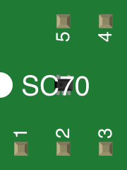
The Hall-effect sensor typically has three pins:
| Pin | Name | Description |
|---|---|---|
| 1 | Vcc | Power supply pin (connect to 3.3V or 5V, depending on the sensor). |
| 2 | GND | Ground pin (connect to circuit ground). |
| 3 | OUT | Output pin (provides voltage proportional to the magnetic field). |
Some advanced Hall-effect sensors may include additional pins for features like enable/disable or analog/digital mode selection.
Usage Instructions
How to Use the Component in a Circuit
- Power the Sensor: Connect the Vcc pin to a regulated power supply (e.g., 5V) and the GND pin to the circuit ground.
- Connect the Output: Attach the OUT pin to an analog input pin of a microcontroller (e.g., Arduino) or to an ADC (Analog-to-Digital Converter) for signal processing.
- Place the Sensor: Position the sensor near the magnetic field source. Ensure the magnetic field is perpendicular to the sensor for optimal detection.
- Read the Output: Measure the voltage at the OUT pin. The voltage will vary based on the strength and polarity of the magnetic field.
Important Considerations and Best Practices
- Magnetic Field Orientation: Ensure the magnetic field is aligned correctly with the sensor's sensitive axis for accurate readings.
- Noise Filtering: Use capacitors (e.g., 0.1 µF) between Vcc and GND to reduce noise in the power supply.
- Temperature Effects: Be aware of temperature variations, as they may slightly affect sensor performance.
- Avoid Overvoltage: Do not exceed the maximum operating voltage to prevent damage to the sensor.
Example: Using a Hall-Effect Sensor with Arduino UNO
Below is an example of how to interface a Hall-effect sensor with an Arduino UNO to detect a magnetic field.
// Example code for interfacing a Hall-effect sensor with Arduino UNO
// Connect the sensor's Vcc to 5V, GND to GND, and OUT to A0 (analog pin).

const int hallSensorPin = A0; // Analog pin connected to the sensor's OUT pin
int sensorValue = 0;          // Variable to store the sensor reading

void setup() {
  Serial.begin(9600); // Initialize serial communication at 9600 baud
}

void loop() {
  sensorValue = analogRead(hallSensorPin); // Read the sensor's output voltage
  float voltage = sensorValue * (5.0 / 1023.0); // Convert ADC value to voltage

  // Print the voltage to the Serial Monitor
  Serial.print("Magnetic Field Voltage: ");
  Serial.print(voltage);
  Serial.println(" V");

  delay(500); // Wait for 500ms before the next reading
}
Troubleshooting and FAQs
Common Issues Users Might Face
No Output Voltage:
- Cause: Incorrect wiring or insufficient power supply.
- Solution: Double-check the connections and ensure the power supply matches the sensor's requirements.
Fluctuating Readings:
- Cause: Electrical noise or unstable power supply.
- Solution: Add a decoupling capacitor (e.g., 0.1 µF) between Vcc and GND.
Low Sensitivity:
- Cause: Weak magnetic field or improper sensor placement.
- Solution: Use a stronger magnet or adjust the sensor's position relative to the magnetic source.
Overheating:
- Cause: Exceeding the maximum voltage or current ratings.
- Solution: Ensure the power supply voltage is within the specified range.
FAQs
Q: Can I use a Hall-effect sensor to measure AC current?
A: Yes, Hall-effect sensors can measure both AC and DC currents when used with a magnetic core or current-carrying conductor.
Q: How do I increase the sensitivity of the sensor?
A: Use a sensor with higher magnetic sensitivity or position the sensor closer to the magnetic source.
Q: Can the sensor detect non-magnetic materials?
A: No, Hall-effect sensors only respond to magnetic fields and cannot detect non-magnetic materials directly.
Q: Is the sensor affected by temperature?
A: Yes, extreme temperatures may slightly affect the sensor's performance. Check the datasheet for temperature compensation features if needed.