How to Use ATS: Examples, Pinouts, and Specs
Introduction
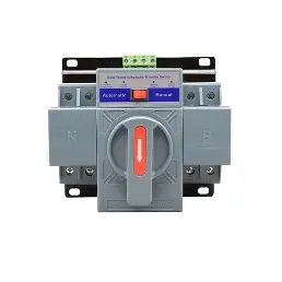
An Automatic Transfer Switch (ATS) is a critical device designed to ensure uninterrupted power supply by automatically transferring a power load between two sources. Typically, it switches between utility power and a backup generator during power outages. The ATS monitors the availability and quality of the primary power source and seamlessly switches to the backup source when necessary, ensuring minimal disruption to connected equipment.
Explore Projects Built with ATS

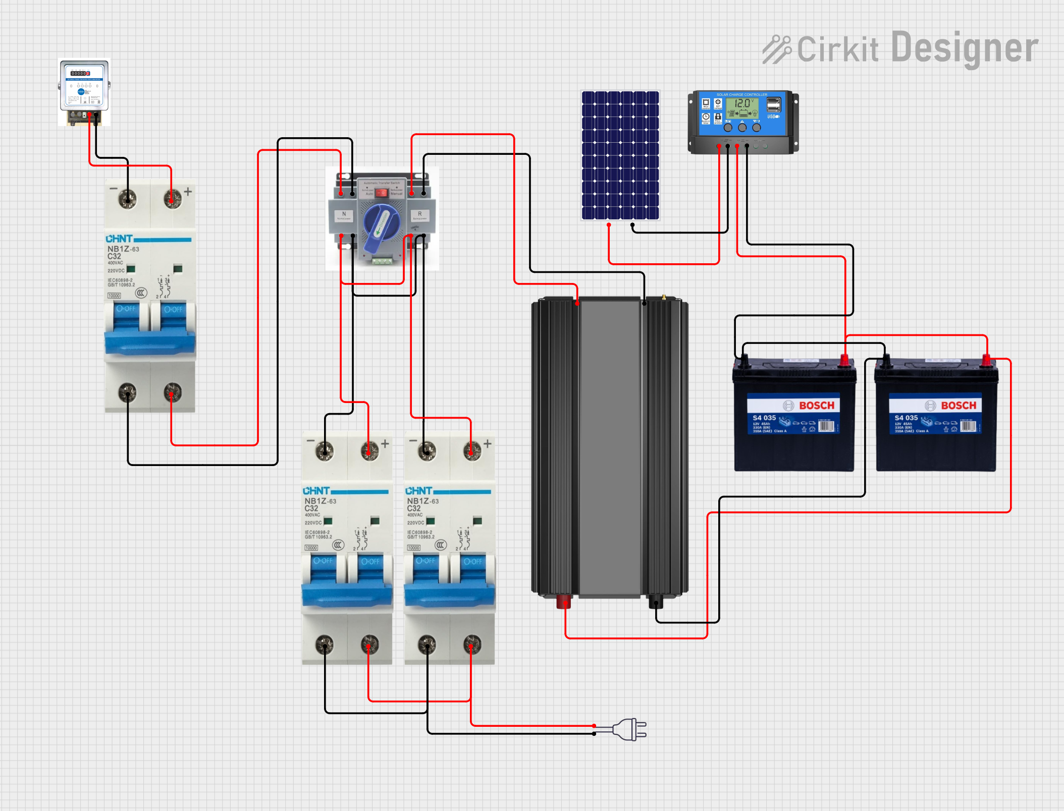
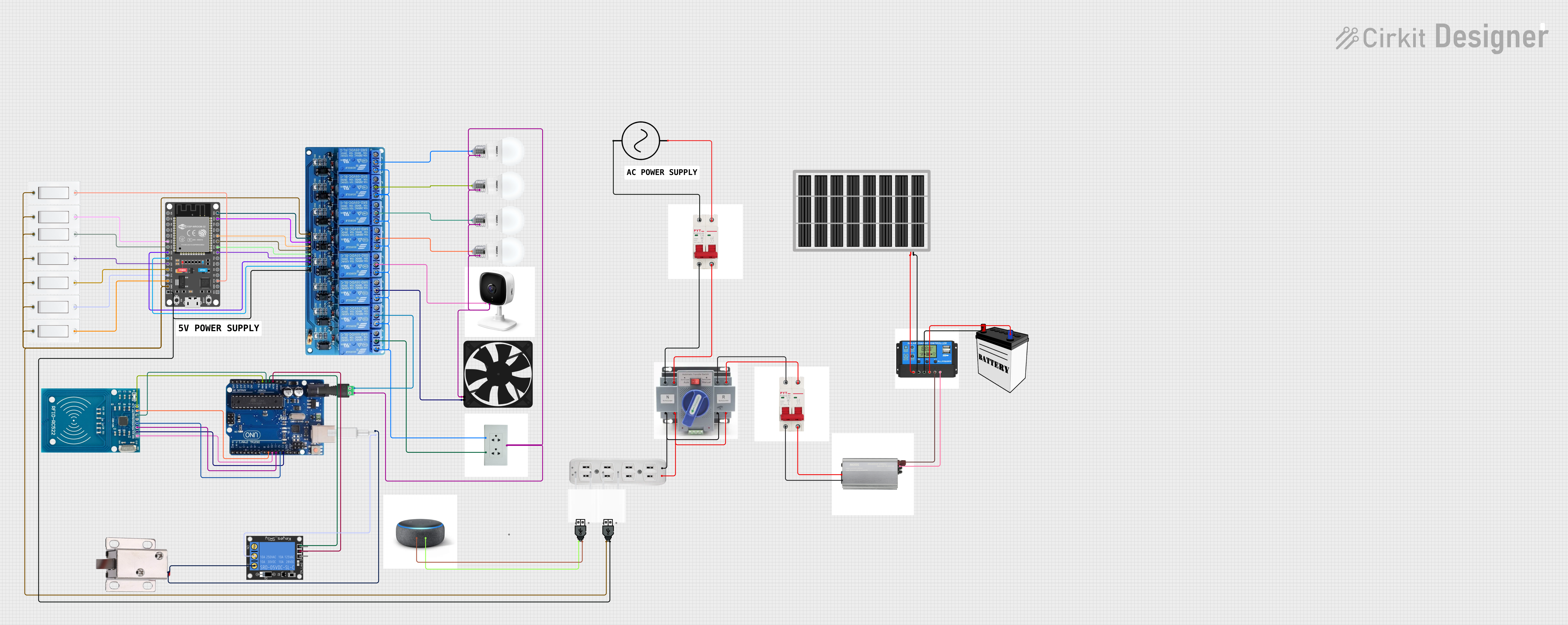

Explore Projects Built with ATS
Common Applications and Use Cases
- Data Centers: Ensures continuous power for servers and critical IT infrastructure.
- Hospitals: Maintains power for life-support systems and essential medical equipment.
- Industrial Facilities: Prevents downtime in manufacturing processes.
- Residential Buildings: Provides backup power for essential home appliances during outages.
- Telecommunication Systems: Keeps communication networks operational during power failures.
Technical Specifications
Below are the key technical details for the ATS:
| Parameter | Value |
|---|---|
| Operating Voltage Range | 120V AC to 480V AC |
| Rated Current Capacity | 50A, 100A, 200A (varies by model) |
| Frequency | 50Hz / 60Hz |
| Transfer Time | < 10 milliseconds |
| Control Voltage | 12V DC / 24V DC |
| Operating Temperature | -20°C to 60°C |
| Enclosure Rating | IP54 (Indoor) / IP65 (Outdoor) |
Pin Configuration and Descriptions
The ATS typically has the following terminal connections:
| Pin/Terminal | Description |
|---|---|
| L1 (Utility) | Line input from the primary utility power source. |
| L2 (Utility) | Neutral input from the primary utility power source. |
| L1 (Generator) | Line input from the backup generator. |
| L2 (Generator) | Neutral input from the backup generator. |
| Load L1 | Line output to the connected load. |
| Load L2 | Neutral output to the connected load. |
| Control Signal | Input for remote control or monitoring signals. |
| Ground | Earth connection for safety. |
Usage Instructions
How to Use the ATS in a Circuit
Installation:
- Ensure the ATS is rated for the voltage and current of your application.
- Mount the ATS in a secure location, away from moisture and excessive heat.
- Connect the utility power source to the L1 (Utility) and L2 (Utility) terminals.
- Connect the backup generator to the L1 (Generator) and L2 (Generator) terminals.
- Connect the load to the Load L1 and Load L2 terminals.
- Ensure proper grounding by connecting the Ground terminal to an earth ground.
Operation:
- The ATS continuously monitors the utility power source.
- When the utility power fails or falls outside acceptable limits, the ATS automatically switches to the backup generator.
- Once the utility power is restored and stable, the ATS switches back to the primary source.
Control and Monitoring:
- Use the Control Signal terminal to integrate the ATS with remote monitoring systems or building management systems (BMS).
Important Considerations and Best Practices
- Safety First: Always disconnect power before installing or servicing the ATS.
- Generator Compatibility: Ensure the backup generator is compatible with the ATS in terms of voltage, frequency, and capacity.
- Testing: Periodically test the ATS to ensure proper operation during power outages.
- Load Balancing: Avoid overloading the ATS by ensuring the connected load does not exceed its rated capacity.
- Surge Protection: Use surge protectors to safeguard the ATS and connected equipment from voltage spikes.
Example: Connecting an ATS to an Arduino UNO
The ATS can be monitored using an Arduino UNO to detect power source changes. Below is an example code snippet:
// ATS Monitoring with Arduino UNO
// This code monitors the ATS status and indicates the active power source
// using LEDs. Connect ATS control signals to Arduino digital pins.

const int utilityPin = 2;  // Pin connected to utility power signal
const int generatorPin = 3; // Pin connected to generator power signal
const int utilityLED = 8;   // LED to indicate utility power is active
const int generatorLED = 9; // LED to indicate generator power is active

void setup() {
  pinMode(utilityPin, INPUT);      // Set utility signal pin as input
  pinMode(generatorPin, INPUT);    // Set generator signal pin as input
  pinMode(utilityLED, OUTPUT);     // Set utility LED pin as output
  pinMode(generatorLED, OUTPUT);   // Set generator LED pin as output
}

void loop() {
  // Read the ATS control signals
  bool utilityStatus = digitalRead(utilityPin);
  bool generatorStatus = digitalRead(generatorPin);

  // Indicate the active power source using LEDs
  if (utilityStatus) {
    digitalWrite(utilityLED, HIGH);  // Turn on utility LED
    digitalWrite(generatorLED, LOW); // Turn off generator LED
  } else if (generatorStatus) {
    digitalWrite(utilityLED, LOW);   // Turn off utility LED
    digitalWrite(generatorLED, HIGH); // Turn on generator LED
  } else {
    // Both sources are inactive
    digitalWrite(utilityLED, LOW);
    digitalWrite(generatorLED, LOW);
  }

  delay(500); // Delay for stability
}
Troubleshooting and FAQs
Common Issues and Solutions
ATS Fails to Switch to Backup Power:
- Cause: Backup generator is not operational or not properly connected.
- Solution: Verify the generator's functionality and connections to the ATS.
Frequent Switching Between Sources:
- Cause: Unstable utility power or incorrect sensitivity settings.
- Solution: Adjust the ATS sensitivity settings or consult the utility provider.
No Power to Load:
- Cause: Loose connections or blown fuses.
- Solution: Inspect all connections and replace any damaged fuses.
Control Signal Not Detected:
- Cause: Faulty wiring or incompatible control voltage.
- Solution: Check the control signal wiring and ensure the voltage matches the ATS specifications.
FAQs
Q: Can the ATS be used with solar power systems?
A: Yes, the ATS can be configured to switch between solar inverters and utility power, provided the voltage and current ratings are compatible.Q: How often should the ATS be tested?
A: It is recommended to test the ATS at least once every three months to ensure proper operation.Q: Can the ATS handle three-phase power?
A: Yes, specific ATS models are designed for three-phase power systems. Ensure you select the correct model for your application.Q: Is professional installation required?
A: While basic installations can be done by experienced users, professional installation is recommended for safety and compliance with local electrical codes.