
How to Use RF-LINK_RX: Examples, Pinouts, and Specs

 Design with RF-LINK_RX in Cirkit Designer
Introduction
The RF-LINK_RX is a radio frequency receiver module designed for wireless communication. It receives signals transmitted over radio waves and converts them into electrical signals for further processing in electronic circuits. This module operates in the unlicensed ISM (Industrial, Scientific, and Medical) frequency bands, making it suitable for a wide range of applications.
Explore Projects Built with RF-LINK_RX
 Open Project in Cirkit Designer
 Open Project in Cirkit Designer
 Open Project in Cirkit Designer
 Open Project in Cirkit Designer
Explore Projects Built with RF-LINK_RX
Open Project in Cirkit DesignerOpen Project in Cirkit DesignerOpen Project in Cirkit DesignerOpen Project in Cirkit DesignerCommon Applications and Use Cases
- Wireless remote controls (e.g., garage doors, home automation)
- Wireless data transmission systems
- Internet of Things (IoT) devices
- Wireless sensor networks
- Alarm and security systems
Technical Specifications
The RF-LINK_RX module is compact and efficient, making it ideal for low-power wireless communication. Below are its key technical details:
Key Technical Details
| Parameter | Value |
|---|---|
| Operating Frequency | 315 MHz / 433 MHz |
| Operating Voltage | 5V DC |
| Operating Current | ≤ 5 mA |
| Sensitivity | -105 dBm |
| Data Rate | Up to 10 kbps |
| Modulation Type | ASK (Amplitude Shift Keying) |
| Operating Temperature | -20°C to +70°C |
| Dimensions | 30mm x 14mm x 7mm |
Pin Configuration and Descriptions
The RF-LINK_RX module typically has 4 pins. Below is the pinout and description:
| Pin Number | Pin Name | Description |
|---|---|---|
| 1 | VCC | Power supply input (5V DC) |
| 2 | DATA | Output pin for received data |
| 3 | GND | Ground connection |
| 4 | ANT | Antenna connection for receiving RF signals |
Usage Instructions
The RF-LINK_RX module is straightforward to use in wireless communication circuits. Below are the steps and best practices for integrating it into your project:
How to Use the RF-LINK_RX in a Circuit
- Power the Module: Connect the
VCCpin to a 5V DC power source and theGNDpin to the ground. - Connect the Data Pin: The
DATApin outputs the received signal. Connect this pin to the input of a microcontroller or decoder IC (e.g., HT12D). - Attach an Antenna: For optimal performance, connect a wire (approximately 17 cm for 433 MHz) to the
ANTpin to act as an antenna. - Pair with a Transmitter: Ensure the RF-LINK_RX module is paired with a compatible RF transmitter module operating at the same frequency (e.g., 433 MHz).
Important Considerations and Best Practices
- Antenna Design: Use a properly tuned antenna for better signal reception. The length of the antenna should match the operating frequency.
- Noise Reduction: Place the module away from high-frequency noise sources to avoid interference.
- Data Decoding: Use a decoder IC or software algorithm to process the received data.
- Power Supply: Ensure a stable 5V power supply to avoid performance issues.
Example: Connecting RF-LINK_RX to an Arduino UNO
Below is an example of how to connect the RF-LINK_RX module to an Arduino UNO and read the received data:
Circuit Connections
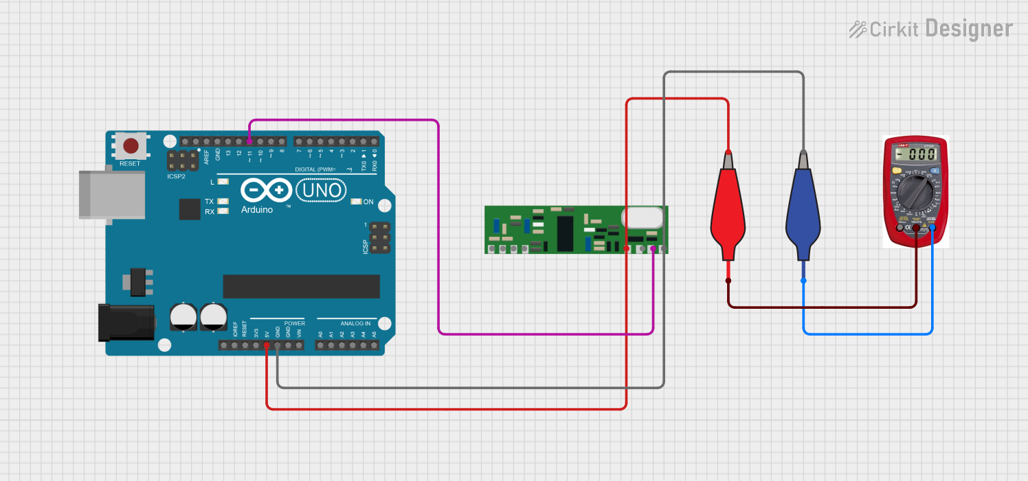
- Connect the
VCCpin of the RF-LINK_RX to the 5V pin of the Arduino. - Connect the
GNDpin of the RF-LINK_RX to the GND pin of the Arduino. - Connect the
DATApin of the RF-LINK_RX to digital pin 2 of the Arduino. - Attach an antenna to the
ANTpin of the RF-LINK_RX.
Arduino Code
// Example code to read data from the RF-LINK_RX module
// Connect the DATA pin of the RF-LINK_RX to Arduino digital pin 2

#define RF_DATA_PIN 2  // Define the pin connected to the DATA pin of RF-LINK_RX

void setup() {
  Serial.begin(9600);  // Initialize serial communication at 9600 baud
  pinMode(RF_DATA_PIN, INPUT);  // Set RF_DATA_PIN as input
  Serial.println("RF-LINK_RX Receiver Ready");
}

void loop() {
  int receivedData = digitalRead(RF_DATA_PIN);  // Read the data pin
  Serial.print("Received Data: ");
  Serial.println(receivedData);  // Print the received data to the Serial Monitor
  delay(100);  // Small delay to avoid flooding the Serial Monitor
}
Troubleshooting and FAQs
Common Issues and Solutions
No Signal Reception:
- Cause: Incorrect antenna length or poor connection.
- Solution: Ensure the antenna is properly connected and matches the operating frequency.
Interference or Noise:
- Cause: Nearby electronic devices causing RF interference.
- Solution: Move the module away from noise sources or use shielding.
Unstable Data Output:
- Cause: Unstable power supply or weak signal.
- Solution: Use a regulated 5V power supply and ensure the transmitter is within range.
No Output on DATA Pin:
- Cause: Incorrect wiring or incompatible transmitter.
- Solution: Double-check the wiring and ensure the transmitter and receiver operate at the same frequency.
FAQs
Q1: Can I use the RF-LINK_RX module with a 3.3V microcontroller?
A1: The RF-LINK_RX module requires a 5V power supply. If your microcontroller operates at 3.3V, use a level shifter for the DATA pin.
Q2: What is the maximum range of the RF-LINK_RX module?
A2: The range depends on the environment and antenna design. In open spaces, it can reach up to 100 meters.
Q3: Can I use multiple RF-LINK_RX modules in the same area?
A3: Yes, but ensure each module is paired with a unique transmitter to avoid interference.
Q4: What type of antenna should I use?
A4: A simple wire antenna (17 cm for 433 MHz) works well. For better performance, use a helical or whip antenna.
By following this documentation, you can effectively integrate the RF-LINK_RX module into your wireless communication projects.