How to Use esp8266 nodemcu : Examples, Pinouts, and Specs
Introduction
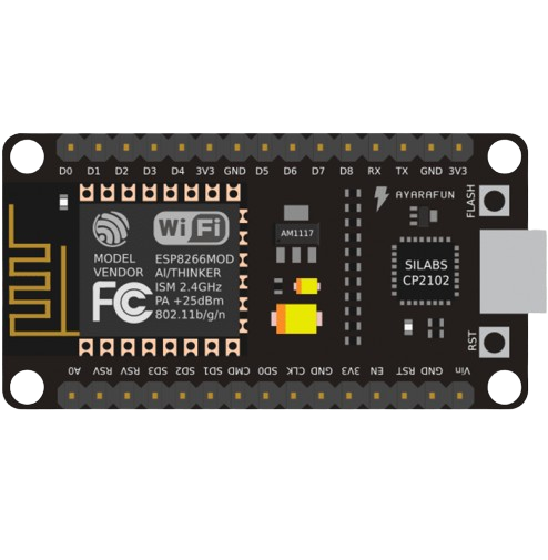
The ESP8266 NodeMCU is an open-source development board that integrates the ESP8266 Wi-Fi module with a USB-to-serial converter, making it a versatile and accessible platform for Internet of Things (IoT) projects and prototypes. It is compatible with the Arduino Integrated Development Environment (IDE), which allows for easy programming and development. The NodeMCU is favored for its Wi-Fi capabilities, compact size, and affordability, making it suitable for a wide range of applications such as home automation, sensor networks, and IoT devices.
Explore Projects Built with esp8266 nodemcu
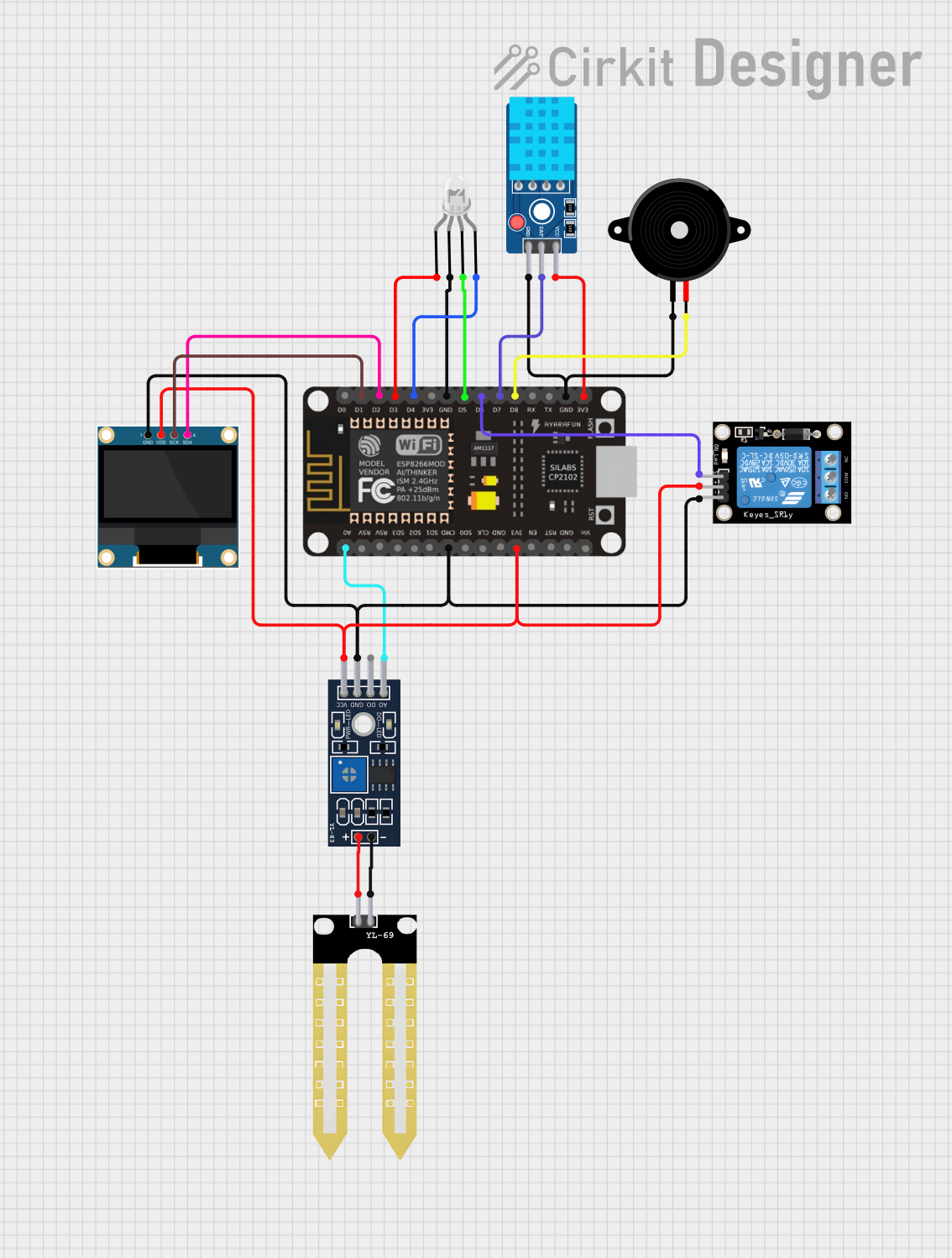

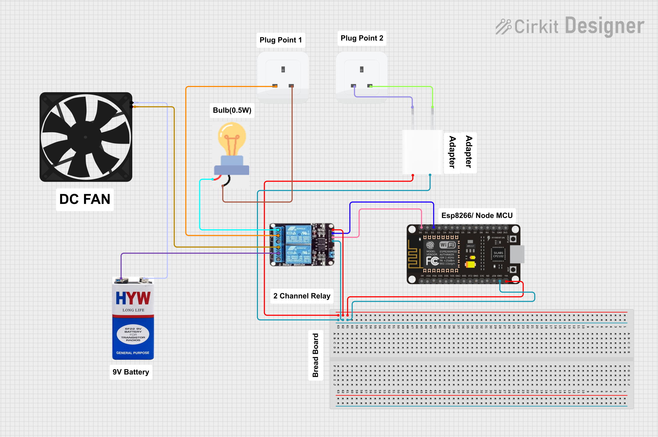
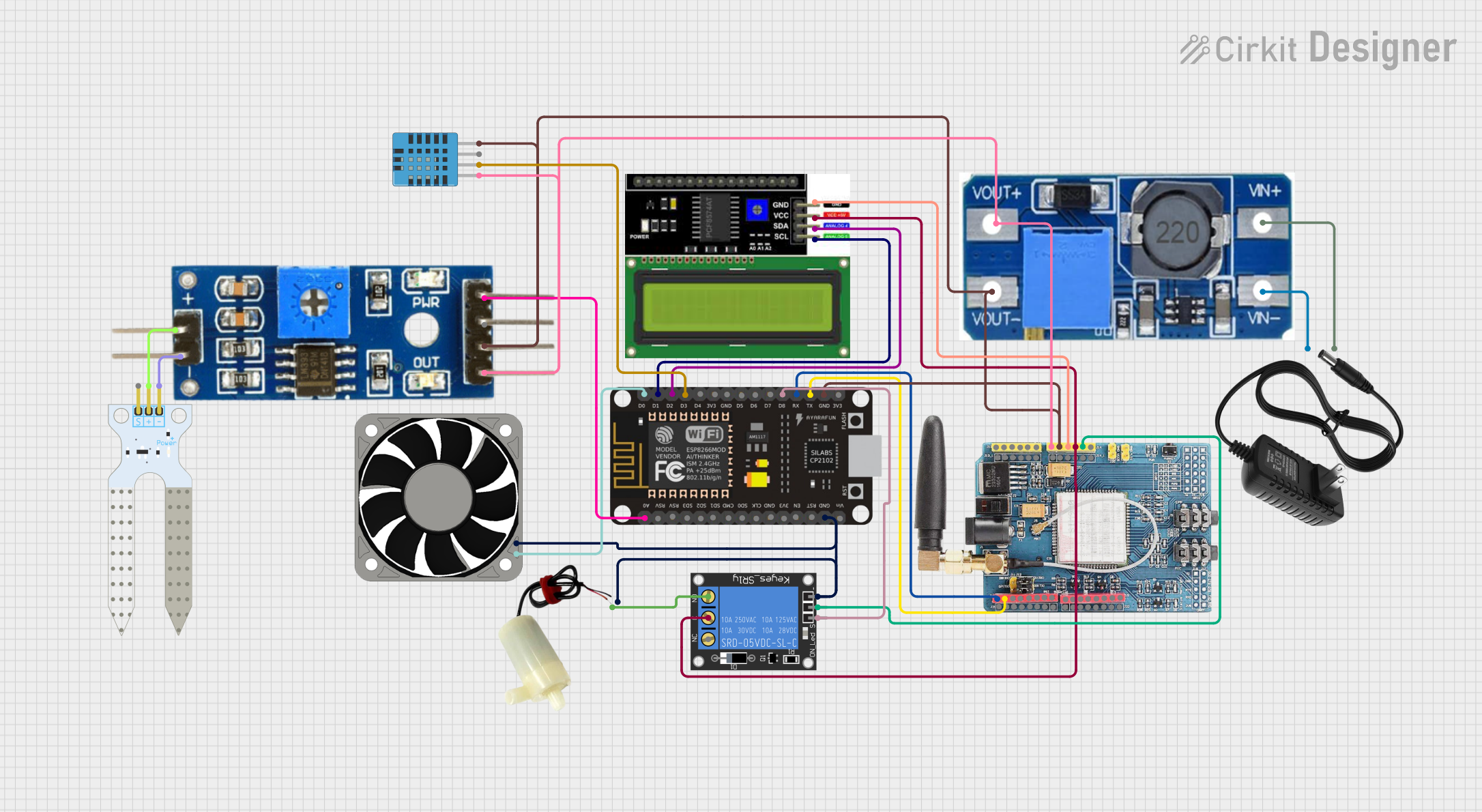
Explore Projects Built with esp8266 nodemcu
Technical Specifications
Key Technical Details
- Microcontroller: ESP8266
- Operating Voltage: 3.3V
- Input Voltage: 7-12V (via Vin pin), 5V (via micro USB)
- Digital I/O Pins: 11, all PWM capable
- Analog Input Pins: 1 (Max input: 3.3V)
- Flash Memory: 4MB
- Clock Speed: 80MHz (can be overclocked to 160MHz)
- Wi-Fi Standards: 802.11 b/g/n
- Wi-Fi Mode: Station/SoftAP/SoftAP+Station
- Programming: Via micro USB port, using Arduino IDE or Lua Script (NodeMCU firmware)
Pin Configuration and Descriptions
| Pin | Function | Description |
|---|---|---|
| GND | Ground | Common ground for power and logic |
| 3V3 | 3.3V Power | Power supply for the board (3.3V) |
| VIN | Voltage Input | External power supply (7-12V) |
| RST | Reset | Resets the module |
| EN | Enable | Chip enable; keep high for normal operation |
| D0-D10 | GPIO | General Purpose Input/Output Pins |
| A0 | ADC | Analog to Digital Converter input |
| TX | UART TX | Transmit pin for UART communication |
| RX | UART RX | Receive pin for UART communication |
| SD2, SD3 | SPI | Used for SPI communication |
| SCL, SDA | I2C | Used for I2C communication |
Usage Instructions
Integrating with a Circuit
Powering the NodeMCU: The NodeMCU can be powered through the USB connection or via the VIN pin with an external power supply. Ensure that the power supply is within the recommended range.
Connecting to Wi-Fi: Utilize the Wi-Fi capabilities of the ESP8266 by using the appropriate libraries in the Arduino IDE to connect to a network.
Programming the NodeMCU: The NodeMCU can be programmed using the Arduino IDE. Select the correct board and port in the IDE, and upload your code using the built-in micro USB port.
Using GPIO Pins: The digital pins can be used for input or output functions. They are also capable of PWM for controlling devices like motors or LEDs.
Analog Reading: The single analog pin (A0) can be used to read analog voltages up to 3.3V.
Best Practices
- Always ensure that the power supply is within the specified range to prevent damage.
- Use a logic level converter when interfacing with components that operate at 5V.
- Avoid drawing too much current from the GPIO pins to prevent damage to the board.
- Utilize proper decoupling capacitors close to the board's power supply pins to minimize noise.
Example Code for Arduino IDE
#include <ESP8266WiFi.h>

// Replace with your network credentials
const char* ssid = "your_SSID";
const char* password = "your_PASSWORD";

void setup() {
  Serial.begin(115200); // Start serial communication at 115200 baud
  WiFi.begin(ssid, password); // Connect to Wi-Fi

  while (WiFi.status() != WL_CONNECTED) { // Wait for connection
    delay(500);
    Serial.print(".");
  }
  Serial.println("");
  Serial.print("Connected to ");
  Serial.println(ssid);
  Serial.print("IP address: ");
  Serial.println(WiFi.localIP());
}

void loop() {
  // Put your main code here, to run repeatedly:
}
Troubleshooting and FAQs
Common Issues
- NodeMCU not connecting to Wi-Fi: Ensure the SSID and password are correct. Check the signal strength and router settings.
- NodeMCU not recognized by computer: Install the correct USB drivers and select the appropriate COM port in the Arduino IDE.
- Unexpected resets or crashes: This can be caused by insufficient power supply or noise. Ensure a stable power source and use decoupling capacitors.
FAQs
Q: Can the NodeMCU be powered by 5V? A: Yes, it can be powered via the micro USB port which accepts 5V, or through the VIN pin if using an external power supply.
Q: How many GPIO pins does the NodeMCU have? A: The NodeMCU has 11 digital I/O pins, all of which are PWM capable.
Q: What is the maximum analog value that can be read on the NodeMCU? A: The A0 pin can read a maximum analog value of 3.3V.
Q: Can the NodeMCU be used with the Arduino IDE? A: Yes, the NodeMCU is fully compatible with the Arduino IDE. Make sure to install the necessary board package via the Boards Manager.
Q: How do I reset the NodeMCU? A: You can reset the NodeMCU by briefly connecting the RST pin to GND or by pressing the onboard reset button.
This documentation provides a comprehensive guide to the ESP8266 NodeMCU, from technical specifications to usage instructions, example code, and troubleshooting tips. Whether you are a beginner or an experienced user, this documentation aims to assist you in your projects and help you make the most of this versatile IoT platform.