How to Use Connection Node 1pin: Examples, Pinouts, and Specs

Introduction
The Connection Node 1pin is a versatile electronic component designed to facilitate single-point electrical connections in circuits. It serves as a modular and reliable interface for connecting various components, such as sensors, actuators, or power sources, to a circuit. Its compact design and ease of use make it an essential component in prototyping, DIY electronics, and modular system designs.
Explore Projects Built with Connection Node 1pin


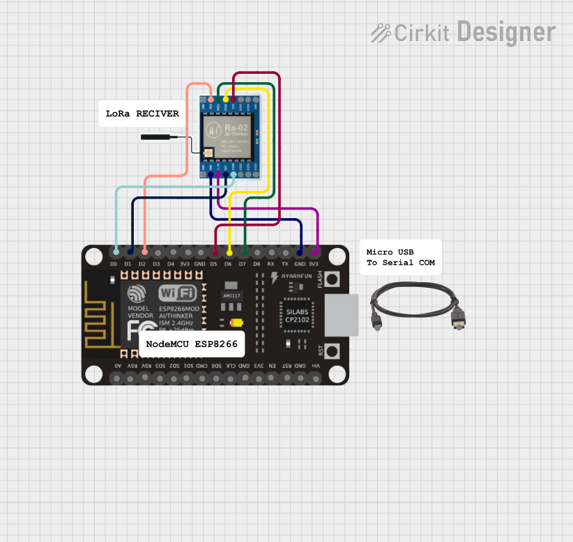
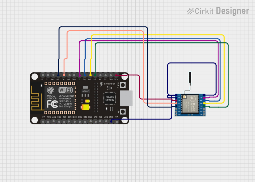
Explore Projects Built with Connection Node 1pin
Common Applications and Use Cases
- Prototyping and breadboarding circuits
- Establishing connections between sensors and microcontrollers
- Modular circuit designs for easy assembly and disassembly
- Extending or splitting single electrical signals
- Educational projects for teaching basic electronics
Technical Specifications
The Connection Node 1pin is a simple yet robust component with the following specifications:
| Parameter | Value |
|---|---|
| Number of Pins | 1 |
| Voltage Rating | 0V to 50V DC |
| Current Rating | Up to 3A |
| Material | Copper (with optional plating) |
| Insulation Resistance | ≥ 100 MΩ |
| Operating Temperature | -40°C to +85°C |
| Dimensions | 2.54mm pitch (standard) |
Pin Configuration and Description
The Connection Node 1pin has a single pin for electrical connection. Below is the pin description:
| Pin Number | Name | Description |
|---|---|---|
| 1 | Signal/Power | Connects to the signal or power line |
Usage Instructions
How to Use the Component in a Circuit
- Identify the Connection Point: Determine where the Connection Node 1pin will be used in your circuit. It can connect a signal line, power line, or ground.
- Insert into Circuit: Place the pin into a breadboard, PCB, or connector socket. Ensure a secure fit to avoid loose connections.
- Connect Wires or Components: Attach the wire or component to the pin. Soldering may be required for permanent connections.
- Verify Connections: Double-check the polarity and ensure the connection is secure before powering the circuit.
Important Considerations and Best Practices
- Avoid Overloading: Ensure the current and voltage do not exceed the specified ratings (3A and 50V DC).
- Secure Connections: For long-term use, solder the pin to prevent accidental disconnections.
- Use Insulation: If the pin is exposed, consider using heat shrink tubing or electrical tape to prevent short circuits.
- Compatibility: Ensure the pin pitch (2.54mm) matches the socket or breadboard you are using.
Example: Connecting to an Arduino UNO
The Connection Node 1pin can be used to connect a sensor or module to an Arduino UNO. Below is an example of connecting a signal line to pin D2 on the Arduino:
Circuit Setup
- Insert the Connection Node 1pin into the breadboard.
- Connect one end of a jumper wire to the Connection Node 1pin.
- Connect the other end of the jumper wire to pin D2 on the Arduino UNO.
Arduino Code Example
// Example code for reading a digital signal from the Connection Node 1pin
const int inputPin = 2; // Pin D2 is connected to the Connection Node 1pin

void setup() {
  pinMode(inputPin, INPUT); // Set pin D2 as an input
  Serial.begin(9600); // Initialize serial communication at 9600 baud
}

void loop() {
  int signalState = digitalRead(inputPin); // Read the signal state
  Serial.print("Signal State: ");
  Serial.println(signalState); // Print the signal state to the Serial Monitor
  delay(500); // Wait for 500ms before reading again
}
Troubleshooting and FAQs
Common Issues and Solutions
Loose Connections
- Issue: The pin is not making a secure connection in the breadboard or socket.
- Solution: Ensure the pin is fully inserted and fits snugly. If necessary, solder the pin for a permanent connection.
Signal Interference
- Issue: The signal is unstable or noisy.
- Solution: Use shorter wires to reduce noise. Add a pull-up or pull-down resistor if needed.
Overheating
- Issue: The pin becomes hot during operation.
- Solution: Check the current and voltage ratings. Reduce the load if it exceeds the specified limits.
Corrosion or Oxidation
- Issue: The pin surface appears tarnished, leading to poor conductivity.
- Solution: Clean the pin with isopropyl alcohol or use a plated version for better durability.
FAQs
Q1: Can the Connection Node 1pin handle AC signals?
A1: Yes, it can handle low-frequency AC signals, but ensure the voltage and current ratings are not exceeded.
Q2: Is the Connection Node 1pin reusable?
A2: Yes, it is reusable, especially in prototyping applications. However, repeated use may degrade the pin's mechanical integrity.
Q3: Can I use this component for high-frequency signals?
A3: The Connection Node 1pin is not optimized for high-frequency signals due to potential impedance issues. For such applications, consider using specialized connectors.
Q4: What tools are needed for soldering the pin?
A4: You will need a soldering iron, solder wire, and optionally, heat shrink tubing for insulation.
By following this documentation, you can effectively integrate the Connection Node 1pin into your electronic projects with ease and confidence.