Cirkit Designer Logo
Cirkit Designer
Your all-in-one circuit design IDE
Home / 
Component Documentation

How to Use FPC 10P: Examples, Pinouts, and Specs

Image of FPC 10P
Cirkit Designer LogoDesign with FPC 10P in Cirkit Designer

Introduction

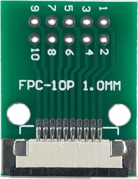
The FPC 10P (Manufacturer Part ID: FPC-10P) is a Flat Printed Circuit (FPC) connector manufactured by MTCELL. This connector features 10 pins and is designed to connect flexible printed circuits to a PCB or other components. Its compact design and flexibility make it ideal for applications where space is limited and a reliable connection is required.

Explore Projects Built with FPC 10P

Use Cirkit Designer to design, explore, and prototype these projects online. Some projects support real-time simulation. Click "Open Project" to start designing instantly!
Optiplex Micro and PoE Camera Surveillance System with Ethernet Switching
Image of Engine Mounts Wiring: A project utilizing FPC 10P in a practical application
This circuit describes a networked system where an Optiplex Micro computer is powered by a PC Power Supply and connected to a PC Screen via HDMI for display output. The computer is networked through an Ethernet Switch, which also connects to two PoE Cameras and a Toyopuc PLC. The Ethernet Switch is powered by a PoE PSU 48V DC, and all AC-powered devices are connected to a common 220V AC source.
Cirkit Designer LogoOpen Project in Cirkit Designer
Battery-Powered FPV Drone with Telemetry and Dual Motor Control
Image of Krul': A project utilizing FPC 10P in a practical application
This circuit appears to be a power distribution and control system for a vehicle with two motorized wheels, possibly a drone or a robot. It includes a lipo battery connected to a Power Distribution Board (PDB) that distributes power to two Electronic Speed Controllers (ESCs) which in turn control the speed and direction of the motors. The system also integrates a flight controller (H743-SLIM V3) for managing various peripherals including GPS, FPV camera system, and a telemetry link (ExpressLRS).
Cirkit Designer LogoOpen Project in Cirkit Designer
Multi-Stage Voltage Regulation and Indicator LED Circuit
Image of Subramanyak_Power_Circuit: A project utilizing FPC 10P in a practical application
This circuit is designed for power management, featuring buck and boost converters for voltage adjustment, and linear regulators for stable voltage output. It includes LEDs for status indication, and terminal blocks for external connections.
Cirkit Designer LogoOpen Project in Cirkit Designer
Satellite Compass and Network-Integrated GPS Data Processing System
Image of GPS 시스템 측정 구성도_241016: A project utilizing FPC 10P in a practical application
This circuit comprises a satellite compass, a mini PC, two GPS antennas, power supplies, a network switch, media converters, and an atomic rubidium clock. The satellite compass is powered by a triple output DC power supply and interfaces with an RS232 splitter for 1PPS signals. The mini PCs are connected to the USRP B200 devices via USB for data and power, and to media converters via Ethernet, which in turn connect to a network switch using fiber optic links. The antennas are connected to the USRP B200s through RF directional couplers, and the atomic clock provides a 1PPS input to the RS232 splitter.
Cirkit Designer LogoOpen Project in Cirkit Designer

Explore Projects Built with FPC 10P

Use Cirkit Designer to design, explore, and prototype these projects online. Some projects support real-time simulation. Click "Open Project" to start designing instantly!
Image of Engine Mounts Wiring: A project utilizing FPC 10P in a practical application
Optiplex Micro and PoE Camera Surveillance System with Ethernet Switching
This circuit describes a networked system where an Optiplex Micro computer is powered by a PC Power Supply and connected to a PC Screen via HDMI for display output. The computer is networked through an Ethernet Switch, which also connects to two PoE Cameras and a Toyopuc PLC. The Ethernet Switch is powered by a PoE PSU 48V DC, and all AC-powered devices are connected to a common 220V AC source.
Cirkit Designer LogoOpen Project in Cirkit Designer
Image of Krul': A project utilizing FPC 10P in a practical application
Battery-Powered FPV Drone with Telemetry and Dual Motor Control
This circuit appears to be a power distribution and control system for a vehicle with two motorized wheels, possibly a drone or a robot. It includes a lipo battery connected to a Power Distribution Board (PDB) that distributes power to two Electronic Speed Controllers (ESCs) which in turn control the speed and direction of the motors. The system also integrates a flight controller (H743-SLIM V3) for managing various peripherals including GPS, FPV camera system, and a telemetry link (ExpressLRS).
Cirkit Designer LogoOpen Project in Cirkit Designer
Image of Subramanyak_Power_Circuit: A project utilizing FPC 10P in a practical application
Multi-Stage Voltage Regulation and Indicator LED Circuit
This circuit is designed for power management, featuring buck and boost converters for voltage adjustment, and linear regulators for stable voltage output. It includes LEDs for status indication, and terminal blocks for external connections.
Cirkit Designer LogoOpen Project in Cirkit Designer
Image of GPS 시스템 측정 구성도_241016: A project utilizing FPC 10P in a practical application
Satellite Compass and Network-Integrated GPS Data Processing System
This circuit comprises a satellite compass, a mini PC, two GPS antennas, power supplies, a network switch, media converters, and an atomic rubidium clock. The satellite compass is powered by a triple output DC power supply and interfaces with an RS232 splitter for 1PPS signals. The mini PCs are connected to the USRP B200 devices via USB for data and power, and to media converters via Ethernet, which in turn connect to a network switch using fiber optic links. The antennas are connected to the USRP B200s through RF directional couplers, and the atomic clock provides a 1PPS input to the RS232 splitter.
Cirkit Designer LogoOpen Project in Cirkit Designer

Common Applications and Use Cases

  • Mobile devices and wearables
  • LCD and OLED display connections
  • Compact consumer electronics
  • Robotics and automation systems
  • Prototyping and development boards

Technical Specifications

Key Technical Details

Parameter Specification
Manufacturer MTCELL
Part ID FPC-10P
Number of Pins 10
Connector Type Flat Printed Circuit (FPC)
Mounting Type Surface Mount (SMT)
Pitch (Pin Spacing) 1.0 mm
Operating Voltage 50V DC
Current Rating 0.5A per pin
Operating Temperature -25°C to +85°C
Contact Material Phosphor Bronze with Gold Plating
Insulation Resistance ≥ 100 MΩ
Durability 20 mating cycles

Pin Configuration and Descriptions

The FPC 10P connector has 10 pins arranged in a single row with a 1.0 mm pitch. Below is the pin configuration:

Pin Number Description
1 Signal/Power Line 1
2 Signal/Power Line 2
3 Signal/Power Line 3
4 Signal/Power Line 4
5 Signal/Power Line 5
6 Signal/Power Line 6
7 Signal/Power Line 7
8 Signal/Power Line 8
9 Signal/Power Line 9
10 Signal/Power Line 10

Note: The specific signal or power assignment for each pin depends on the application and circuit design.

Usage Instructions

How to Use the FPC 10P in a Circuit

  1. PCB Design: Ensure the PCB has a compatible footprint for the FPC 10P connector. The pin pitch should match the 1.0 mm spacing.
  2. Soldering: Use surface-mount soldering techniques to attach the connector to the PCB. Reflow soldering is recommended for precision.
  3. FPC Insertion:
    • Open the connector's locking mechanism (if applicable).
    • Insert the flexible printed circuit (FPC) into the connector, ensuring proper alignment.
    • Close the locking mechanism to secure the FPC in place.
  4. Testing: Verify the connection using a multimeter or continuity tester to ensure all pins are properly connected.

Important Considerations and Best Practices

  • Alignment: Ensure the FPC is aligned correctly with the connector to avoid damage to the pins.
  • Soldering Temperature: Follow the manufacturer's recommended soldering temperature profile to prevent overheating.
  • Durability: Avoid excessive mating and unmating cycles, as the connector is rated for 20 cycles.
  • Cleaning: Keep the connector free from dust and debris to maintain reliable connections.

Example: Connecting FPC 10P to an Arduino UNO

The FPC 10P can be used to connect an external module (e.g., an LCD display) to an Arduino UNO. Below is an example code snippet for interfacing an LCD module via the FPC 10P connector:

#include <LiquidCrystal.h>

// Initialize the LCD with the pins connected via the FPC 10P connector
// RS, EN, D4, D5, D6, D7 are connected to Arduino pins 7, 8, 9, 10, 11, 12
LiquidCrystal lcd(7, 8, 9, 10, 11, 12);

void setup() {
  // Set up the LCD's number of columns and rows
  lcd.begin(16, 2);
  
  // Print a message to the LCD
  lcd.print("Hello, FPC 10P!");
}

void loop() {
  // Move the cursor to the second row and print a message
  lcd.setCursor(0, 1);
  lcd.print("MTCELL Connector");
}

Note: Ensure the FPC 10P connector is properly soldered to the PCB and connected to the Arduino UNO pins as specified in the code.

Troubleshooting and FAQs

Common Issues and Solutions

  1. Loose Connection:

    • Issue: The FPC is not securely connected to the FPC 10P connector.
    • Solution: Check the locking mechanism and ensure the FPC is fully inserted and locked.
  2. Signal Interference:

    • Issue: Noise or interference in the signal lines.
    • Solution: Use shorter FPC cables and ensure proper grounding in the circuit.
  3. Damaged Pins:

    • Issue: Pins are bent or damaged during insertion.
    • Solution: Handle the connector and FPC with care. Replace the connector if pins are irreparably damaged.
  4. Soldering Issues:

    • Issue: Poor solder joints causing intermittent connections.
    • Solution: Inspect solder joints under a microscope and reflow solder if necessary.

FAQs

Q1: Can the FPC 10P handle high-current applications?
A1: No, the FPC 10P is rated for 0.5A per pin. For high-current applications, consider using a connector with a higher current rating.

Q2: Is the FPC 10P compatible with 0.5 mm pitch FPCs?
A2: No, the FPC 10P is designed for 1.0 mm pitch FPCs. Ensure the FPC matches the connector's pitch.

Q3: Can I use the FPC 10P in outdoor environments?
A3: The FPC 10P is not specifically designed for outdoor use. If used outdoors, ensure it is protected from moisture and extreme temperatures.

Q4: How do I clean the FPC 10P connector?
A4: Use a soft brush or compressed air to remove dust. Avoid using liquids or abrasive materials.

By following this documentation, users can effectively integrate the MTCELL FPC 10P connector into their projects and troubleshoot common issues with ease.