How to Use ADXL345: Examples, Pinouts, and Specs
Introduction
The ADXL345 is a small, thin, low-power 3-axis accelerometer capable of high-resolution (13-bit) measurements at up to ±16g. It is designed for applications requiring precise motion sensing, tilt detection, and gesture recognition. The device supports both I2C and SPI communication protocols, making it versatile and easy to integrate into a wide range of projects.
Explore Projects Built with ADXL345
Explore Projects Built with ADXL345
Common Applications
- Motion sensing in mobile devices
- Tilt detection in gaming controllers
- Gesture recognition in wearable devices
- Vibration monitoring in industrial equipment
- Free-fall detection in safety systems
Technical Specifications
The ADXL345 offers a robust set of features and specifications that make it suitable for various applications. Below are the key technical details:
Key Specifications
| Parameter | Value |
|---|---|
| Supply Voltage (VDD) | 2.0V to 3.6V |
| I/O Voltage (VDDIO) | 1.7V to VDD |
| Measurement Range | ±2g, ±4g, ±8g, ±16g |
| Resolution | 13-bit |
| Communication Protocols | I2C (up to 400 kHz), SPI (up to 5 MHz) |
| Operating Temperature | -40°C to +85°C |
| Power Consumption | 40 µA in measurement mode, 0.1 µA in standby mode |
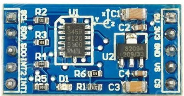
Pin Configuration
The ADXL345 is typically available in a 14-pin LGA package. Below is the pin configuration:
| Pin Number | Pin Name | Description |
|---|---|---|
| 1 | VDD | Power supply (2.0V to 3.6V) |
| 2 | GND | Ground |
| 3 | CS | Chip Select (SPI mode) |
| 4 | INT1 | Interrupt 1 output |
| 5 | INT2 | Interrupt 2 output |
| 6 | SDO/ALT_ADDR | SPI Data Out / I2C Alternate Address Select |
| 7 | SDA/SDI/SDIO | I2C Data / SPI Data In / Data I/O |
| 8 | SCL/SCLK | I2C Clock / SPI Clock |
| 9-14 | NC | No Connection |
Usage Instructions
The ADXL345 can be used in a variety of circuits and applications. Below are the steps and considerations for using the component effectively.
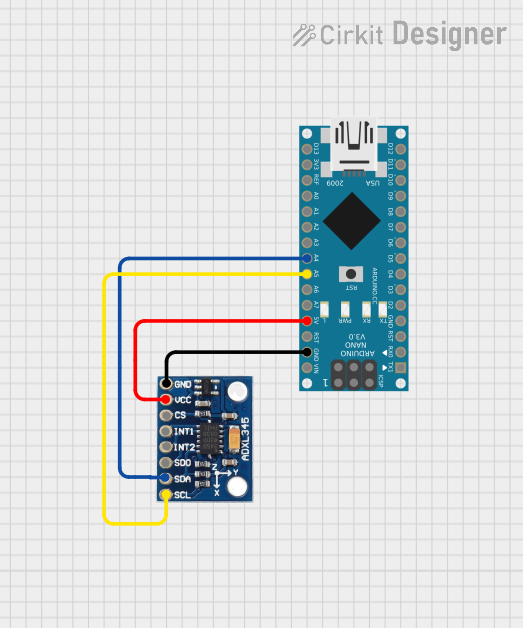
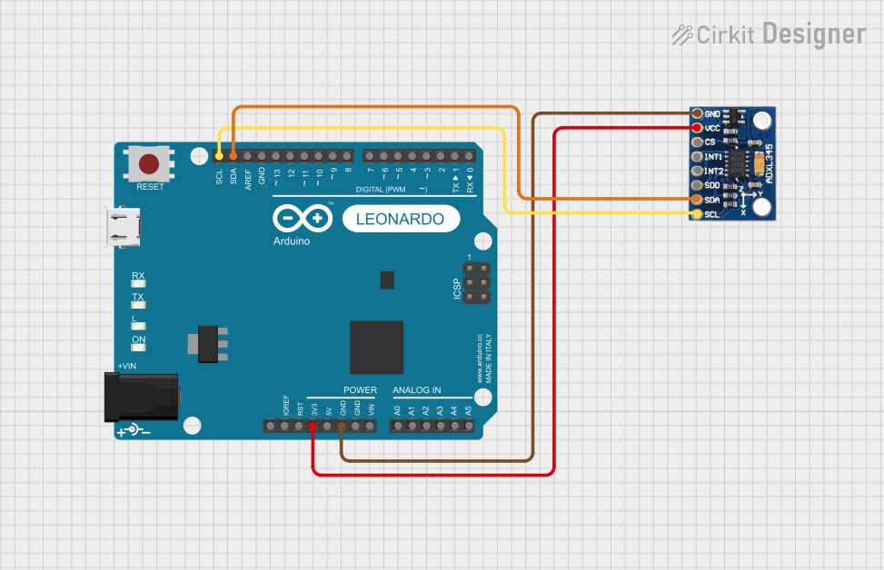
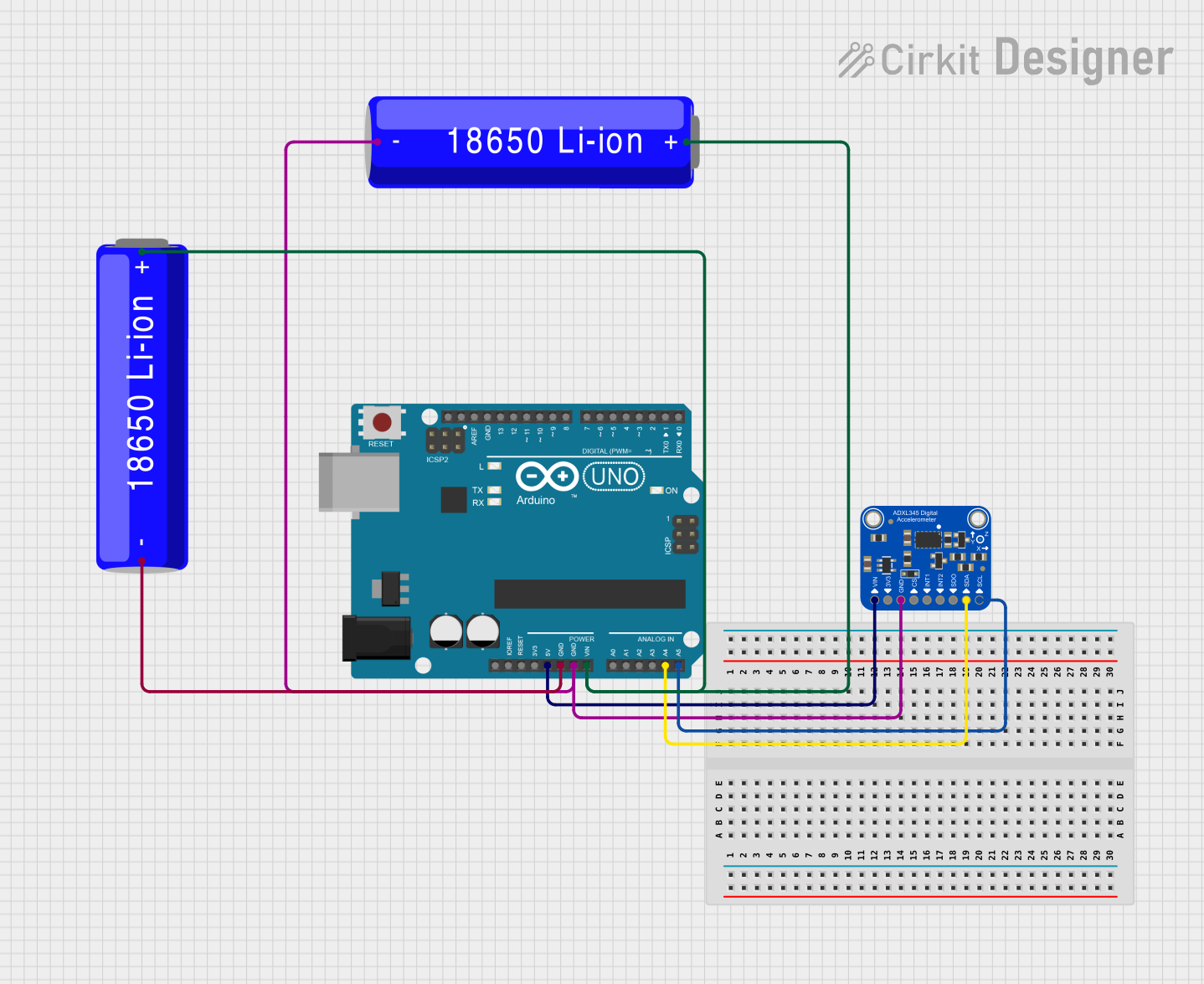
Connecting the ADXL345 to an Arduino UNO
The ADXL345 can communicate with an Arduino UNO using the I2C protocol. Follow these steps to connect the device:
Wiring:
- Connect the
VDDpin of the ADXL345 to the 3.3V pin on the Arduino. - Connect the
GNDpin of the ADXL345 to the GND pin on the Arduino. - Connect the
SDApin of the ADXL345 to the A4 pin on the Arduino (I2C data line). - Connect the
SCLpin of the ADXL345 to the A5 pin on the Arduino (I2C clock line). - If using the I2C alternate address, connect the
SDO/ALT_ADDRpin to GND.
- Connect the
Install Required Libraries:
- Install the
Adafruit_ADXL345library from the Arduino Library Manager.
- Install the
Example Code: Below is an example Arduino sketch to read acceleration data from the ADXL345:
#include <Wire.h>
#include <Adafruit_Sensor.h>
#include <Adafruit_ADXL345_U.h>

// Create an ADXL345 object
Adafruit_ADXL345_Unified accel = Adafruit_ADXL345_Unified(12345);

void setup() {
  Serial.begin(9600);
  // Initialize the ADXL345
  if (!accel.begin()) {
    Serial.println("Failed to find ADXL345 chip");
    while (1); // Halt if the sensor is not detected
  }
  Serial.println("ADXL345 initialized successfully!");

  // Set the range to ±16g
  accel.setRange(ADXL345_RANGE_16_G);
  Serial.println("Range set to ±16g");
}

void loop() {
  sensors_event_t event;
  accel.getEvent(&event);

  // Print acceleration data
  Serial.print("X: "); Serial.print(event.acceleration.x); Serial.print(" m/s^2 ");
  Serial.print("Y: "); Serial.print(event.acceleration.y); Serial.print(" m/s^2 ");
  Serial.print("Z: "); Serial.print(event.acceleration.z); Serial.println(" m/s^2");

  delay(500); // Delay for readability
}
Important Considerations
- Power Supply: Ensure the ADXL345 is powered within its specified voltage range (2.0V to 3.6V). Exceeding this range may damage the device.
- Pull-Up Resistors: When using I2C, ensure pull-up resistors (typically 4.7kΩ) are connected to the SDA and SCL lines.
- Interrupt Pins: The
INT1andINT2pins can be configured for specific events, such as free-fall detection or activity monitoring.
Troubleshooting and FAQs
Common Issues
No Data Output:
- Cause: Incorrect wiring or communication protocol mismatch.
- Solution: Double-check the connections and ensure the correct protocol (I2C or SPI) is selected.
Inconsistent Readings:
- Cause: Noise or improper grounding.
- Solution: Use decoupling capacitors near the power pins and ensure a solid ground connection.
Device Not Detected:
- Cause: Incorrect I2C address or faulty sensor.
- Solution: Verify the I2C address (default is
0x53) and try scanning for devices using an I2C scanner sketch.
FAQs
Can the ADXL345 operate at 5V?
- No, the ADXL345 operates at a maximum of 3.6V. Use a level shifter if interfacing with a 5V system.
How do I change the measurement range?
- Use the
setRange()function in the library to set the range to ±2g, ±4g, ±8g, or ±16g.
- Use the
What is the default I2C address of the ADXL345?
- The default I2C address is
0x53. It can be changed to0x1Dby connecting theSDO/ALT_ADDRpin to VDD.
- The default I2C address is
By following this documentation, you can effectively integrate the ADXL345 into your projects for reliable motion sensing and acceleration measurements.