How to Use Rotary Encoder Knob with Push Button: Examples, Pinouts, and Specs
Introduction
A rotary encoder knob is a versatile input device that allows users to control variables such as volume, brightness, or menu navigation by rotating the knob. Unlike potentiometers, rotary encoders provide digital signals, making them ideal for applications requiring precise and incremental adjustments. Many rotary encoders also include a built-in push button, which adds an extra layer of functionality, such as selecting options or confirming actions.
Explore Projects Built with Rotary Encoder Knob with Push Button
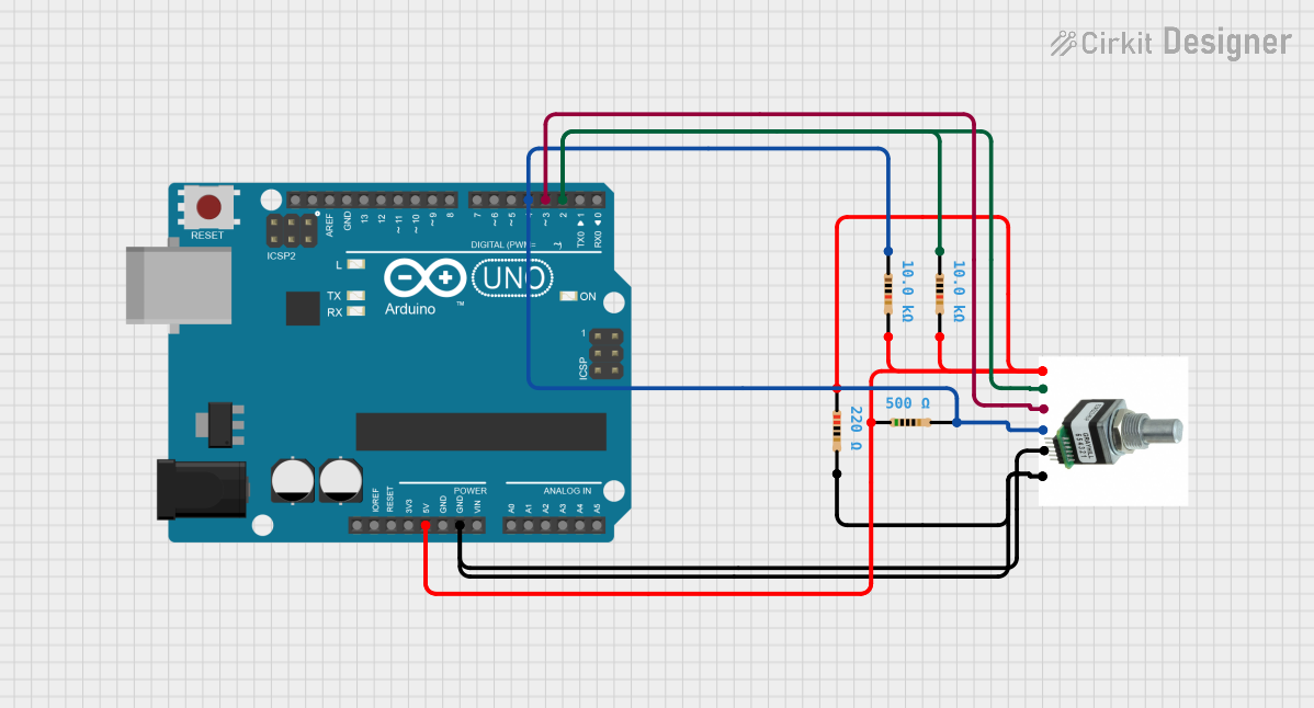
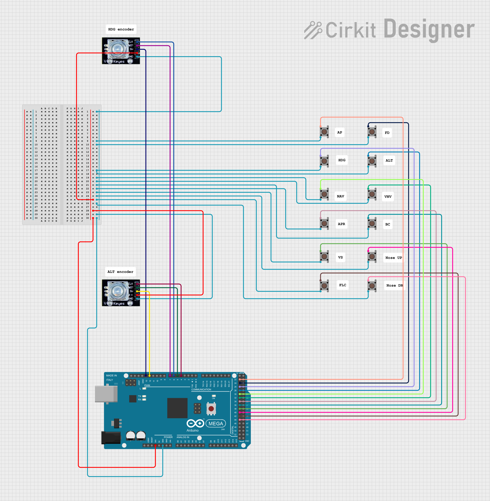
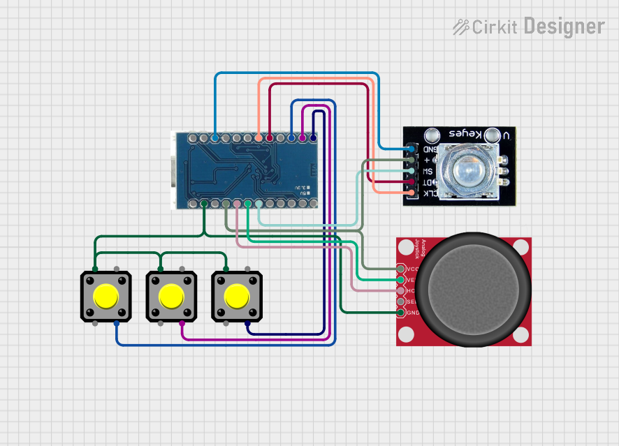
Explore Projects Built with Rotary Encoder Knob with Push Button
Common Applications
- Audio equipment for volume and tone control
- User interfaces for menu navigation
- Robotics for precise motor control
- Industrial equipment for parameter adjustments
- DIY electronics projects and prototyping
Technical Specifications
Key Technical Details
- Operating Voltage: 3.3V to 5V
- Output Type: Digital (quadrature signals)
- Push Button Type: Momentary, normally open
- Rotational Steps: Typically 20 or 30 steps per revolution (varies by model)
- Debouncing: Required for stable signal processing
- Shaft Type: Knurled or smooth, with optional detents
- Mounting: PCB mount or panel mount
Pin Configuration and Descriptions
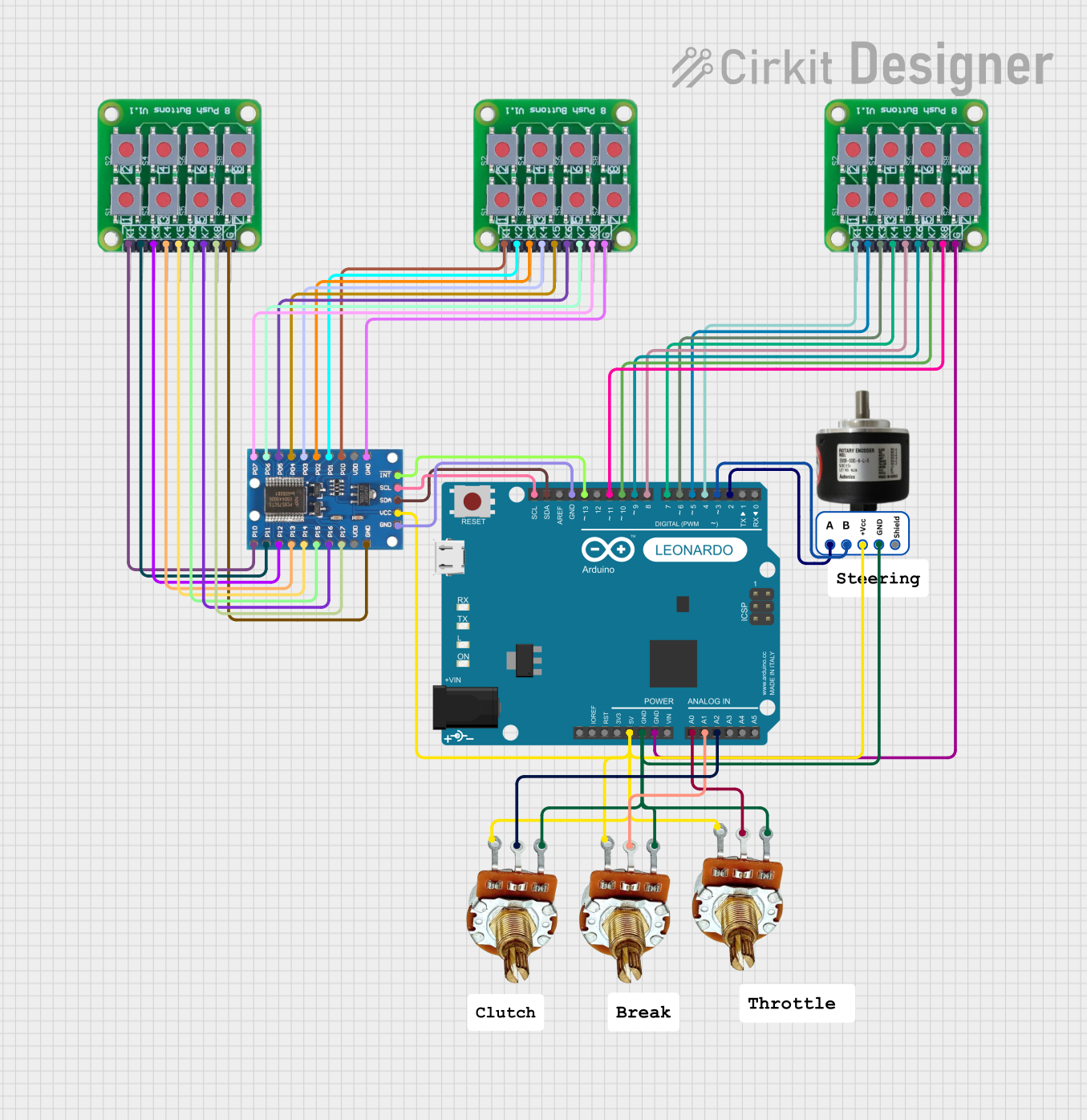
The rotary encoder typically has 5 pins: three for the encoder and two for the push button. Below is the pinout:
| Pin Name | Description | Connection |
|---|---|---|
| GND | Ground pin for the encoder and button | Connect to GND |
| VCC | Power supply pin (3.3V or 5V) | Connect to 3.3V or 5V |
| CLK (A) | Clock signal output (Channel A) | Connect to microcontroller GPIO |
| DT (B) | Data signal output (Channel B) | Connect to microcontroller GPIO |
| SW | Push button signal output | Connect to microcontroller GPIO |
Usage Instructions
How to Use the Component in a Circuit
Wiring the Rotary Encoder:
- Connect the VCC pin to the 3.3V or 5V power supply of your microcontroller.
- Connect the GND pin to the ground of your circuit.
- Connect the CLK (A) and DT (B) pins to two GPIO pins on your microcontroller.
- Connect the SW pin to another GPIO pin to read the push button state.
Debouncing:
- Rotary encoders and push buttons often produce noisy signals. Use hardware (capacitors) or software (debouncing algorithms) to filter out noise.
Reading the Encoder:
- Monitor the CLK (A) and DT (B) signals to determine the direction of rotation.
- A change in the signal sequence (e.g., A leads B or B leads A) indicates clockwise or counterclockwise rotation.
Using the Push Button:
- Read the state of the SW pin to detect button presses. Use pull-up or pull-down resistors if necessary.
Arduino UNO Example Code
Below is an example of how to use a rotary encoder with a push button on an Arduino UNO:
// Rotary Encoder Pins
#define CLK 2  // Connect to CLK (A) pin of the encoder
#define DT 3   // Connect to DT (B) pin of the encoder
#define SW 4   // Connect to SW pin of the encoder

int counter = 0;  // Variable to store the encoder count
int currentStateCLK;
int lastStateCLK;
bool buttonPressed = false;

void setup() {
  pinMode(CLK, INPUT);
  pinMode(DT, INPUT);
  pinMode(SW, INPUT_PULLUP);  // Use internal pull-up resistor for the button

  // Read the initial state of CLK
  lastStateCLK = digitalRead(CLK);

  Serial.begin(9600);  // Initialize serial communication
}

void loop() {
  // Read the current state of CLK
  currentStateCLK = digitalRead(CLK);

  // If the state of CLK has changed, check the direction
  if (currentStateCLK != lastStateCLK) {
    // If DT state is different from CLK state, the encoder is rotating CW
    if (digitalRead(DT) != currentStateCLK) {
      counter++;
    } else {
      counter--;
    }

    // Print the counter value
    Serial.print("Counter: ");
    Serial.println(counter);
  }

  // Update lastStateCLK to the current state
  lastStateCLK = currentStateCLK;

  // Check if the button is pressed
  if (digitalRead(SW) == LOW) {
    if (!buttonPressed) {
      Serial.println("Button Pressed!");
      buttonPressed = true;
    }
  } else {
    buttonPressed = false;
  }
}
Important Considerations and Best Practices
- Debouncing: Use capacitors or software to debounce the encoder and button signals.
- Power Supply: Ensure the encoder operates within its specified voltage range (3.3V or 5V).
- Signal Stability: Use pull-up or pull-down resistors if the signals are unstable.
- Mechanical Wear: Rotary encoders are mechanical devices and may wear out over time. Use them within their rated lifespan.
Troubleshooting and FAQs
Common Issues and Solutions
The encoder is not registering rotation:
- Check the wiring connections for the CLK and DT pins.
- Ensure the encoder is powered correctly (3.3V or 5V).
- Verify that the microcontroller GPIO pins are configured as inputs.
The push button is not working:
- Ensure the SW pin is connected to a GPIO pin with a pull-up or pull-down resistor.
- Check for mechanical issues with the button.
The encoder skips steps or behaves erratically:
- Add debouncing to the CLK and DT signals using capacitors or software.
- Verify that the encoder is not damaged or worn out.
The direction of rotation is reversed:
- Swap the connections of the CLK and DT pins.
FAQs
Q: Can I use the rotary encoder with a 3.3V microcontroller?
A: Yes, most rotary encoders are compatible with both 3.3V and 5V systems. Check the datasheet for your specific model.
Q: Do I need external pull-up resistors for the push button?
A: Not necessarily. You can use the internal pull-up resistors of your microcontroller by configuring the pin as INPUT_PULLUP.
Q: How do I debounce the encoder signals in software?
A: Implement a delay or use a state machine to filter out rapid signal changes caused by noise.
Q: Can I use the encoder for high-speed applications?
A: Rotary encoders are suitable for moderate-speed applications. For high-speed use, ensure your microcontroller can process the signals fast enough.