How to Use 6-60V 400W DC Three-Phase Brushless Motor Speed Controller: Examples, Pinouts, and Specs

Introduction
The 6-60V 400W DC Three-Phase Brushless Motor Speed Controller (Manufacturer: RANSANX, Part ID: B0F1YGJ48F) is a versatile and efficient device designed to regulate the speed and direction of three-phase brushless DC (BLDC) motors. It operates within a wide voltage range of 6 to 60 volts and supports a maximum power output of 400 watts, making it suitable for a variety of applications.
Explore Projects Built with 6-60V 400W DC Three-Phase Brushless Motor Speed Controller
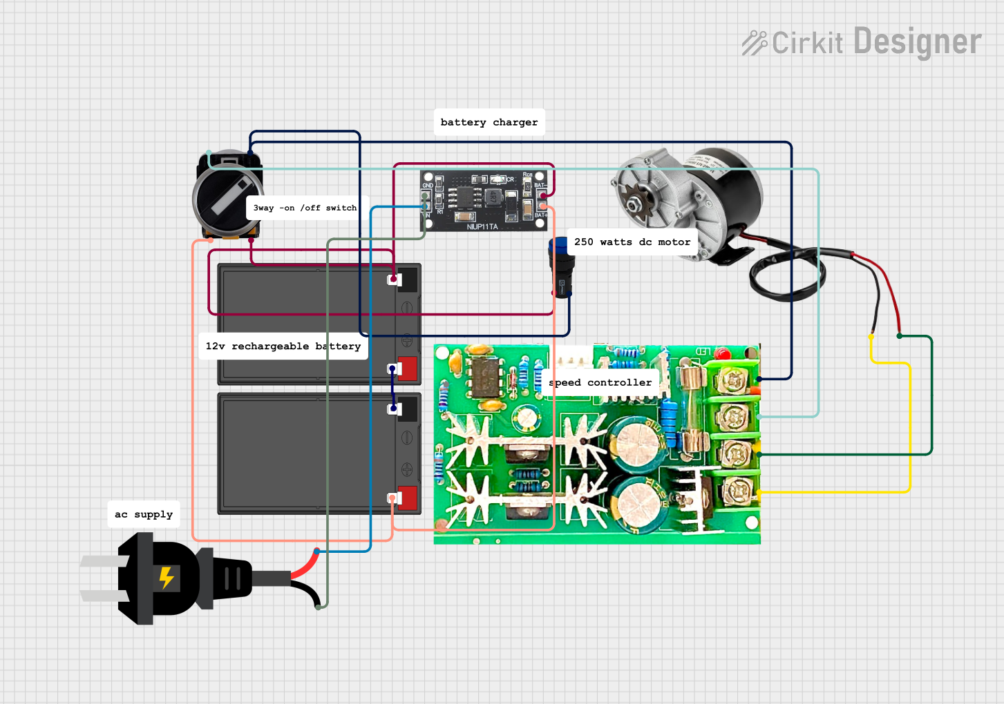

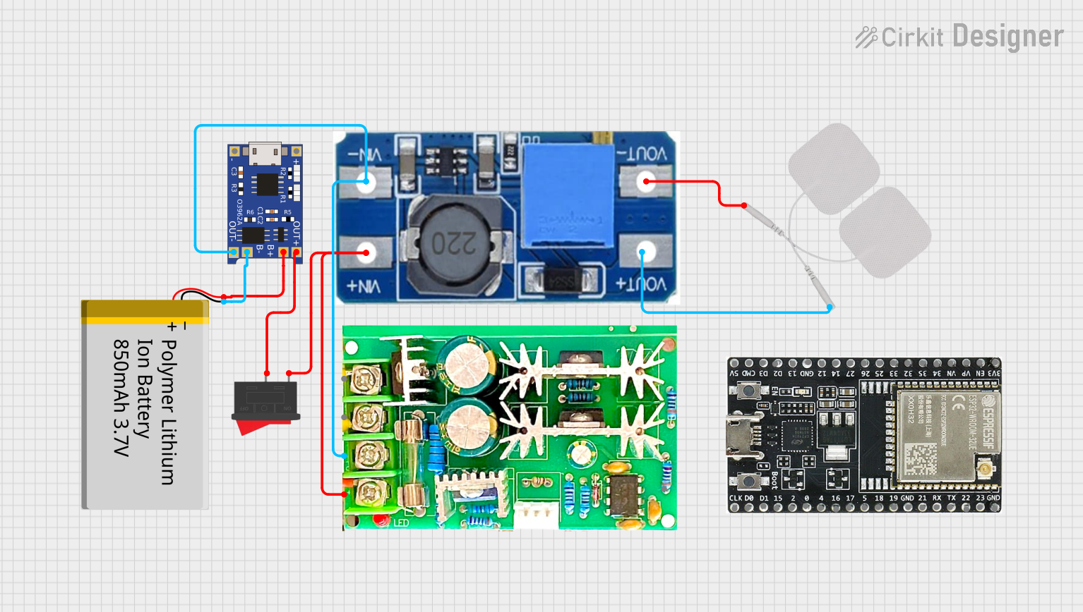

Explore Projects Built with 6-60V 400W DC Three-Phase Brushless Motor Speed Controller
Common Applications and Use Cases
- Electric bicycles and scooters
- RC vehicles and drones
- Industrial automation systems
- Conveyor belts and robotic arms
- Fans, pumps, and other motor-driven devices
This controller is ideal for projects requiring precise motor speed control, high efficiency, and reliable operation.
Technical Specifications
Key Technical Details
| Parameter | Specification |
|---|---|
| Input Voltage Range | 6V to 60V DC |
| Maximum Power Output | 400W |
| Motor Type Supported | Three-phase brushless DC motor |
| Control Mode | PWM (Pulse Width Modulation) |
| Speed Adjustment Range | 0% to 100% |
| Direction Control | Forward and reverse supported |
| Operating Temperature | -20°C to 50°C |
| Dimensions | 85mm x 60mm x 28mm |
Pin Configuration and Descriptions
The controller has several input and output connections for power, motor, and control signals. Below is the pin configuration:
Power and Motor Connections
| Pin Label | Description |
|---|---|
+V |
Positive DC input (6V to 60V) |
-V |
Negative DC input (ground) |
U |
Motor phase U connection |
V |
Motor phase V connection |
W |
Motor phase W connection |
Control Signal Connections
| Pin Label | Description |
|---|---|
PWM |
PWM input for speed control |
DIR |
Direction control input (forward/reverse) |
GND |
Ground for control signals |
Usage Instructions
How to Use the Component in a Circuit
- Power Supply Connection: Connect a DC power supply (6V to 60V) to the
+Vand-Vterminals. Ensure the power supply can provide sufficient current for the motor's operation. - Motor Connection: Connect the three-phase brushless DC motor to the
U,V, andWterminals. Ensure the motor's voltage and power ratings are compatible with the controller. - Control Signal Connection:
- Connect a PWM signal (e.g., from a microcontroller) to the
PWMpin to control the motor speed. - Use the
DIRpin to set the motor's direction. A HIGH signal typically sets forward direction, while a LOW signal sets reverse direction. - Connect the
GNDpin to the ground of the control signal source.
- Connect a PWM signal (e.g., from a microcontroller) to the
- Speed Adjustment: Adjust the PWM duty cycle to control the motor speed. A higher duty cycle corresponds to a higher speed.
Important Considerations and Best Practices
- Voltage Compatibility: Ensure the input voltage matches the motor's operating voltage range.
- Heat Dissipation: The controller may generate heat during operation. Use proper heat sinks or cooling mechanisms if necessary.
- Wiring: Use appropriate wire gauges for power and motor connections to handle the current without overheating.
- Startup Testing: Test the setup with a low-speed setting initially to verify proper operation before increasing the speed.
Example: Using with Arduino UNO
The controller can be easily interfaced with an Arduino UNO for motor speed and direction control. Below is an example code snippet:
// Define pins for PWM and direction control
const int pwmPin = 9;  // PWM output pin
const int dirPin = 8;  // Direction control pin

void setup() {
  pinMode(pwmPin, OUTPUT);  // Set PWM pin as output
  pinMode(dirPin, OUTPUT);  // Set direction pin as output

  // Set initial direction to forward
  digitalWrite(dirPin, HIGH);
}

void loop() {
  // Gradually increase motor speed
  for (int speed = 0; speed <= 255; speed++) {
    analogWrite(pwmPin, speed);  // Set PWM duty cycle
    delay(20);  // Wait for 20ms
  }

  // Gradually decrease motor speed
  for (int speed = 255; speed >= 0; speed--) {
    analogWrite(pwmPin, speed);  // Set PWM duty cycle
    delay(20);  // Wait for 20ms
  }

  // Reverse motor direction
  digitalWrite(dirPin, LOW);  // Set direction to reverse
  delay(1000);  // Wait for 1 second

  // Repeat the process
}
Troubleshooting and FAQs
Common Issues and Solutions
Motor Does Not Start:
- Check the power supply voltage and ensure it is within the specified range.
- Verify all connections, especially the motor phase wires (
U,V,W). - Ensure the PWM signal is being generated correctly.
Motor Runs in the Wrong Direction:
- Check the
DIRpin signal. Toggle the signal to change the direction. - Verify the motor phase connections (
U,V,W) are correct.
- Check the
Overheating:
- Ensure proper ventilation or use a heat sink for the controller.
- Check for excessive current draw from the motor.
Inconsistent Speed Control:
- Verify the PWM signal's frequency and duty cycle.
- Ensure the ground (
GND) of the controller and the control signal source are connected.
FAQs
Q: Can this controller be used with a single-phase motor?
A: No, this controller is specifically designed for three-phase brushless DC motors.
Q: What is the recommended PWM frequency?
A: A PWM frequency between 1 kHz and 20 kHz is typically recommended for smooth motor operation.
Q: Can I use this controller with a battery-powered system?
A: Yes, as long as the battery voltage is within the 6V to 60V range and can supply sufficient current.
Q: Is reverse braking supported?
A: No, this controller does not support active braking. It only controls speed and direction.
This documentation provides a comprehensive guide to using the 6-60V 400W DC Three-Phase Brushless Motor Speed Controller effectively. For further assistance, refer to the manufacturer's datasheet or contact RANSANX support.