
How to Use 74HCT157: Examples, Pinouts, and Specs
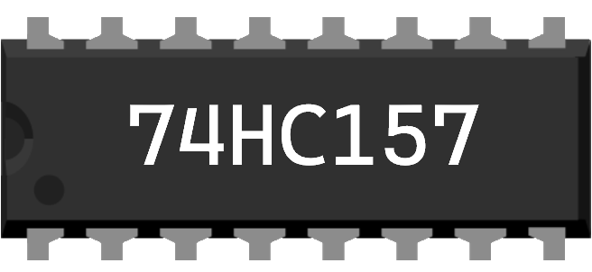
 Design with 74HCT157 in Cirkit Designer
Introduction
The 74HCT157 is a quad 2-input multiplexer designed for high-speed operation and low power consumption. It features four independent 2-to-1 multiplexers, each capable of selecting one of two data inputs based on a common binary selection input. This component is widely used in digital circuits for data routing, signal selection, and logic design.
Explore Projects Built with 74HCT157
 Open Project in Cirkit Designer
 Open Project in Cirkit Designer
 Open Project in Cirkit Designer
 Open Project in Cirkit Designer
Explore Projects Built with 74HCT157
Open Project in Cirkit DesignerOpen Project in Cirkit DesignerOpen Project in Cirkit DesignerOpen Project in Cirkit DesignerCommon Applications
- Data routing in digital systems
- Signal selection in microcontroller-based projects
- Logic function implementation
- Multiplexing in communication systems
- Address decoding in memory circuits
Technical Specifications
The 74HCT157 is part of the 74HCT logic family, which is compatible with TTL (Transistor-Transistor Logic) voltage levels. Below are the key technical details:
| Parameter | Value |
|---|---|
| Supply Voltage (Vcc) | 4.5V to 5.5V |
| Input Voltage Range | 0V to Vcc |
| High-Level Input Voltage | Min 2.0V |
| Low-Level Input Voltage | Max 0.8V |
| High-Level Output Voltage | Min Vcc - 0.1V (at Iout = -4mA) |
| Low-Level Output Voltage | Max 0.1V (at Iout = 4mA) |
| Propagation Delay (typical) | 15ns (at Vcc = 5V) |
| Power Consumption | Low |
| Operating Temperature Range | -40°C to +125°C |
Pin Configuration and Descriptions
The 74HCT157 is available in a 16-pin DIP (Dual Inline Package) or other package types. Below is the pinout and description:
| Pin Number | Pin Name | Description |
|---|---|---|
| 1 | A/B | Select Input (Binary Selector) |
| 2 | 1A | Data Input A for MUX 1 |
| 3 | 1B | Data Input B for MUX 1 |
| 4 | 1Y | Output for MUX 1 |
| 5 | 2A | Data Input A for MUX 2 |
| 6 | 2B | Data Input B for MUX 2 |
| 7 | 2Y | Output for MUX 2 |
| 8 | GND | Ground (0V) |
| 9 | 3Y | Output for MUX 3 |
| 10 | 3B | Data Input B for MUX 3 |
| 11 | 3A | Data Input A for MUX 3 |
| 12 | 4Y | Output for MUX 4 |
| 13 | 4B | Data Input B for MUX 4 |
| 14 | 4A | Data Input A for MUX 4 |
| 15 | Enable (E) | Active-Low Enable Input (must be LOW to operate) |
| 16 | Vcc | Positive Supply Voltage |
Usage Instructions
How to Use the 74HCT157 in a Circuit
- Power Supply: Connect the Vcc pin (16) to a 5V power supply and the GND pin (8) to ground.
- Enable Input: Ensure the Enable (E) pin (15) is connected to a LOW signal (logic 0) to activate the multiplexer. If this pin is HIGH, all outputs will be disabled.
- Data Inputs: Connect the desired data signals to the A and B inputs (e.g., 1A, 1B, etc.).
- Select Input: Use the A/B pin (1) to select between the A and B inputs for all four multiplexers:
- Logic 0: Outputs (Y) will reflect the A inputs.
- Logic 1: Outputs (Y) will reflect the B inputs.
- Outputs: Connect the output pins (e.g., 1Y, 2Y, etc.) to the desired destination in your circuit.
Important Considerations
- Input Voltage Levels: Ensure that the input signals are within the specified voltage range (0V to Vcc).
- Enable Pin: The Enable pin must be LOW for the device to function. If left floating, the behavior may be unpredictable.
- Decoupling Capacitor: Place a 0.1µF ceramic capacitor close to the Vcc pin to stabilize the power supply and reduce noise.
- Unused Inputs: Tie any unused inputs (A, B, or Enable) to a defined logic level (HIGH or LOW) to avoid floating inputs, which can cause erratic behavior.
Example: Connecting to an Arduino UNO
The 74HCT157 can be easily interfaced with an Arduino UNO for digital signal selection. Below is an example code snippet:
// Define pin connections
const int selectPin = 2;  // Arduino pin connected to A/B (pin 1)
const int enablePin = 3;  // Arduino pin connected to Enable (pin 15)
const int inputA = 4;     // Arduino pin connected to 1A (pin 2)
const int inputB = 5;     // Arduino pin connected to 1B (pin 3)
const int outputY = 6;    // Arduino pin connected to 1Y (pin 4)

void setup() {
  // Set pin modes
  pinMode(selectPin, OUTPUT);
  pinMode(enablePin, OUTPUT);
  pinMode(inputA, OUTPUT);
  pinMode(inputB, OUTPUT);
  pinMode(outputY, INPUT);

  // Initialize pins
  digitalWrite(enablePin, LOW);  // Enable the multiplexer
  digitalWrite(inputA, LOW);     // Set initial state for input A
  digitalWrite(inputB, HIGH);    // Set initial state for input B
}

void loop() {
  // Select input A
  digitalWrite(selectPin, LOW);  // A/B = 0, output reflects input A
  delay(1000);                   // Wait for 1 second

  // Select input B
  digitalWrite(selectPin, HIGH); // A/B = 1, output reflects input B
  delay(1000);                   // Wait for 1 second
}
Troubleshooting and FAQs
Common Issues
No Output Signal:
- Ensure the Enable (E) pin is connected to a LOW signal.
- Verify that the power supply (Vcc and GND) is properly connected.
- Check the input signals to ensure they are within the specified voltage range.
Erratic Behavior:
- Ensure all unused inputs are tied to a defined logic level (HIGH or LOW).
- Add a decoupling capacitor (0.1µF) near the Vcc pin to reduce noise.
Incorrect Output:
- Verify the logic level on the A/B select pin.
- Check the connections to the A and B input pins for proper wiring.
FAQs
Q: Can the 74HCT157 operate at 3.3V?
A: No, the 74HCT157 is designed for a supply voltage range of 4.5V to 5.5V. For 3.3V operation, consider using a compatible CMOS multiplexer like the 74HC157.
Q: What happens if the Enable pin is left floating?
A: Leaving the Enable pin floating can result in unpredictable behavior. Always tie it to a defined logic level (LOW to enable, HIGH to disable).
Q: Can I use the 74HCT157 for analog signals?
A: No, the 74HCT157 is designed for digital signals only. For analog multiplexing, consider using an analog multiplexer like the CD4051.
Q: How fast can the 74HCT157 switch between inputs?
A: The typical propagation delay is 15ns at 5V, making it suitable for high-speed digital applications.