How to Use 1.77 1.8 TFT LCD SPI st7735 128x160: Examples, Pinouts, and Specs
Introduction
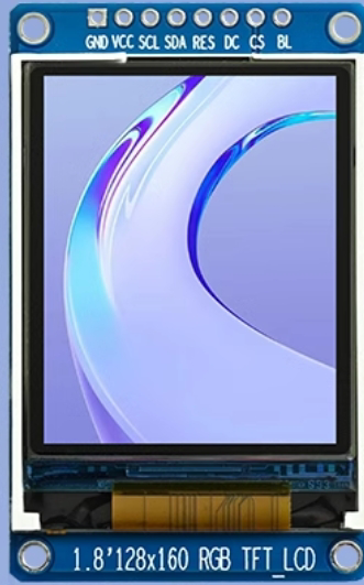
The 1.77" 1.8" TFT LCD SPI ST7735 is a compact color display module with a resolution of 128x160 pixels. It is powered by the ST7735 driver and communicates via the SPI (Serial Peripheral Interface) protocol. This module is widely used in embedded systems for displaying text, images, and graphical data. Its small size, vibrant color display, and low power consumption make it ideal for portable devices, DIY projects, and IoT applications.
Explore Projects Built with 1.77 1.8 TFT LCD SPI st7735 128x160


Explore Projects Built with 1.77 1.8 TFT LCD SPI st7735 128x160
Common Applications and Use Cases
- Portable devices and handheld gadgets
- IoT dashboards and data visualization
- Wearable electronics
- Gaming consoles and retro gaming projects
- Educational and prototyping purposes
Technical Specifications
Key Technical Details
| Parameter | Value |
|---|---|
| Display Type | TFT LCD |
| Driver IC | ST7735 |
| Resolution | 128x160 pixels |
| Communication Protocol | SPI (Serial Peripheral Interface) |
| Operating Voltage | 3.3V (logic level) |
| Backlight Voltage | 3.3V to 5V |
| Current Consumption | ~50mA (with backlight on) |
| Display Size | 1.77" or 1.8" diagonal |
| Color Depth | 18-bit (262,144 colors) |
| Viewing Angle | ~160° |
| Operating Temperature | -20°C to 70°C |
Pin Configuration and Descriptions
| Pin Name | Pin Number | Description |
|---|---|---|
| GND | 1 | Ground connection |
| VCC | 2 | Power supply (3.3V to 5V for backlight) |
| SCL | 3 | Serial Clock (SPI clock input) |
| SDA | 4 | Serial Data (SPI data input) |
| RES | 5 | Reset pin (active low) |
| DC | 6 | Data/Command control pin |
| CS | 7 | Chip Select (active low) |
| BLK | 8 | Backlight control (connect to VCC for always on) |
Usage Instructions
How to Use the Component in a Circuit
- Power Supply: Connect the
VCCpin to a 3.3V or 5V power source and theGNDpin to ground. - SPI Communication: Connect the
SCL(clock) andSDA(data) pins to the corresponding SPI pins on your microcontroller. - Control Pins:
- Connect the
RESpin to a GPIO pin for resetting the display. - Use the
DCpin to toggle between data and command modes. - Connect the
CSpin to a GPIO pin to enable or disable the display.
- Connect the
- Backlight: Connect the
BLKpin toVCCfor constant backlight or to a PWM pin for brightness control.
Important Considerations and Best Practices
- Voltage Levels: Ensure that the logic level of your microcontroller matches the display's operating voltage (3.3V). Use a level shifter if necessary.
- SPI Speed: Configure the SPI clock speed according to the ST7735 datasheet to avoid communication errors.
- Initialization: Always initialize the display using the correct sequence of commands as specified in the ST7735 datasheet.
- Backlight Control: Use a PWM signal on the
BLKpin to adjust the brightness and reduce power consumption.
Example Code for Arduino UNO
Below is an example of how to interface the display with an Arduino UNO using the Adafruit ST7735 library:
#include <Adafruit_GFX.h>    // Core graphics library
#include <Adafruit_ST7735.h> // ST7735 driver library
#include <SPI.h>             // SPI library

// Define pin connections
#define TFT_CS     10  // Chip Select pin
#define TFT_RST    9   // Reset pin
#define TFT_DC     8   // Data/Command pin

// Initialize the display object
Adafruit_ST7735 tft = Adafruit_ST7735(TFT_CS, TFT_DC, TFT_RST);

void setup() {
  // Initialize serial communication for debugging
  Serial.begin(9600);
  Serial.println("Initializing display...");

  // Initialize the display
  tft.initR(INITR_BLACKTAB); // Use INITR_BLACKTAB for this display
  tft.fillScreen(ST77XX_BLACK); // Clear the screen with black color

  // Display a test message
  tft.setTextColor(ST77XX_WHITE); // Set text color to white
  tft.setTextSize(1);             // Set text size
  tft.setCursor(0, 0);            // Set cursor position
  tft.println("Hello, World!");   // Print text to the display
}

void loop() {
  // Add your code here to update the display
}
Notes:
- Install the Adafruit GFX and Adafruit ST7735 libraries via the Arduino Library Manager before running the code.
- Adjust the pin definitions (
TFT_CS,TFT_RST,TFT_DC) to match your wiring.
Troubleshooting and FAQs
Common Issues and Solutions
No Display Output:
- Verify all connections, especially the SPI pins.
- Ensure the
CS,DC, andRESpins are correctly connected and configured. - Check the power supply voltage and current.
Flickering or Distorted Display:
- Reduce the SPI clock speed in your code.
- Ensure proper grounding between the display and the microcontroller.
Backlight Not Turning On:
- Confirm that the
BLKpin is connected toVCCor a PWM pin. - Check the backlight voltage (3.3V to 5V).
- Confirm that the
Incorrect Colors or Graphics:
- Ensure the display is initialized with the correct command sequence.
- Verify that the color format (e.g., RGB565) matches the library settings.
FAQs
Q: Can I use this display with a 5V microcontroller like Arduino UNO?
A: Yes, but you need to use level shifters for the SPI and control pins to step down the 5V logic to 3.3V.
Q: How do I display images on this screen?
A: Convert your image to a compatible format (e.g., RGB565) and use the Adafruit GFX library's drawBitmap() or drawRGBBitmap() functions.
Q: Can I control the backlight brightness?
A: Yes, connect the BLK pin to a PWM-capable pin on your microcontroller and adjust the duty cycle.
Q: Is this display compatible with Raspberry Pi?
A: Yes, it can be used with Raspberry Pi via SPI, but you may need to install additional libraries like luma.lcd or Pillow.
By following this documentation, you can effectively integrate the 1.77" 1.8" TFT LCD SPI ST7735 display into your projects!