How to Use B0303S-1WR3 1W Isolated DC-DC Converter 3.3V→5V: Examples, Pinouts, and Specs
Introduction
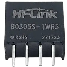
The B0503S-1WR3 is a compact, high-efficiency isolated DC-DC converter manufactured by Shenzhen Hi-Link Electronic Co., Ltd. This module is designed to step up a 3.3V DC input to a stable 5V DC output, delivering up to 1W of power. Its small size and high reliability make it ideal for powering low-power devices in applications such as industrial control systems, IoT devices, and embedded systems.
Explore Projects Built with B0303S-1WR3 1W Isolated DC-DC Converter 3.3V→5V


Explore Projects Built with B0303S-1WR3 1W Isolated DC-DC Converter 3.3V→5V
Common Applications
- Powering microcontrollers and sensors in embedded systems
- Isolated power supply for industrial control circuits
- Voltage level conversion in IoT devices
- Medical instrumentation and portable electronics
Technical Specifications
Key Specifications
| Parameter | Value |
|---|---|
| Input Voltage Range | 3.3V DC ± 10% |
| Output Voltage | 5V DC |
| Output Power | 1W |
| Output Current | 200mA (max) |
| Efficiency | Up to 80% |
| Isolation Voltage | 1500V DC |
| Operating Temperature | -40°C to +85°C |
| Package Type | SIP-4 (Single Inline Package) |
| Dimensions | 11.6mm x 6mm x 10mm |
Pin Configuration and Descriptions
The B0503S-1WR3 has a 4-pin SIP (Single Inline Package) configuration. The pinout is as follows:
| Pin Number | Pin Name | Description |
|---|---|---|
| 1 | VIN+ | Positive input voltage (3.3V DC) |
| 2 | VIN- | Negative input voltage (Ground) |
| 3 | VOUT- | Negative output voltage (Ground) |
| 4 | VOUT+ | Positive output voltage (5V DC) |
Usage Instructions
How to Use the Component in a Circuit
- Input Voltage Connection: Connect the 3.3V DC input to the
VIN+pin and the ground to theVIN-pin. Ensure the input voltage is within the specified range (3.3V ± 10%) to avoid damage. - Output Voltage Connection: Connect the load to the
VOUT+andVOUT-pins. The module will provide a stable 5V DC output. - Bypass Capacitors: For optimal performance, place a 10µF capacitor across the input pins (
VIN+andVIN-) and a 10µF capacitor across the output pins (VOUT+andVOUT-). These capacitors help reduce noise and improve stability. - Isolation: The module provides 1500V DC isolation between the input and output, making it suitable for applications requiring electrical isolation.
Important Considerations and Best Practices
- Load Requirements: Ensure the load does not exceed the maximum output current of 200mA.
- Thermal Management: Operate the module within the specified temperature range (-40°C to +85°C). If used in high-temperature environments, ensure adequate ventilation or heat dissipation.
- Polarity: Double-check the polarity of the input and output connections. Reversing the polarity may damage the module.
- Testing: Before integrating the module into a final design, test it on a breadboard or prototype circuit to verify performance.
Example: Using the B0503S-1WR3 with an Arduino UNO
The B0503S-1WR3 can be used to power an Arduino UNO from a 3.3V source. Below is an example circuit and code:
Circuit Connections
- Connect the 3.3V source to
VIN+andVIN-of the B0503S-1WR3. - Connect the
VOUT+pin to the Arduino UNO's5Vpin. - Connect the
VOUT-pin to the Arduino UNO'sGNDpin.
Example Code
// Example code to blink an LED using Arduino UNO powered by B0503S-1WR3
// Ensure the B0503S-1WR3 is providing a stable 5V to the Arduino UNO.

const int ledPin = 13; // Pin connected to the onboard LED

void setup() {
  pinMode(ledPin, OUTPUT); // Set the LED pin as an output
}

void loop() {
  digitalWrite(ledPin, HIGH); // Turn the LED on
  delay(1000);                // Wait for 1 second
  digitalWrite(ledPin, LOW);  // Turn the LED off
  delay(1000);                // Wait for 1 second
}
Troubleshooting and FAQs
Common Issues and Solutions
| Issue | Possible Cause | Solution |
|---|---|---|
| No output voltage | Incorrect input voltage or polarity | Verify input voltage and polarity. |
| Output voltage is unstable | Insufficient bypass capacitors | Add 10µF capacitors to input and output. |
| Module overheating | Excessive load or poor ventilation | Reduce load or improve ventilation. |
| Output voltage too low or too high | Input voltage out of range | Ensure input voltage is 3.3V ± 10%. |
FAQs
Can the B0503S-1WR3 be used with a 5V input?
- No, the module is designed specifically for a 3.3V input. Using a 5V input may damage the module.
What is the maximum distance between the module and the load?
- For best performance, keep the distance as short as possible to minimize voltage drops and noise.
Can I use this module to power a Wi-Fi module?
- Yes, as long as the Wi-Fi module's power requirements do not exceed 5V and 200mA.
Is the module protected against reverse polarity?
- No, the module does not have built-in reverse polarity protection. Always double-check connections before powering the circuit.
This concludes the documentation for the B0503S-1WR3 1W Isolated DC-DC Converter. For further assistance, refer to the manufacturer's datasheet or contact Shenzhen Hi-Link Electronic Co., Ltd.