Cirkit Designer Logo
Cirkit Designer
Your all-in-one circuit design IDE
Home / 
Component Documentation

How to Use LM2596: Examples, Pinouts, and Specs

Image of LM2596
Cirkit Designer LogoDesign with LM2596 in Cirkit Designer

Introduction

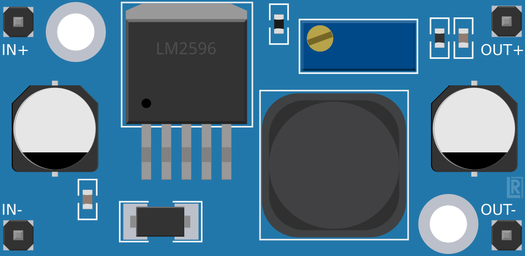
The LM2596 is a step-down (buck) voltage regulator designed to efficiently convert a higher input voltage into a stable, lower output voltage. It is capable of delivering up to 3A of output current, making it ideal for powering a wide range of electronic devices. With its wide input voltage range (4.5V to 40V) and high efficiency, the LM2596 is commonly used in power supply circuits, battery chargers, and embedded systems.

Explore Projects Built with LM2596

Use Cirkit Designer to design, explore, and prototype these projects online. Some projects support real-time simulation. Click "Open Project" to start designing instantly!
ESP32-Based Solar-Powered Current Monitoring System with OLED Display
Image of Solar Tracker and Monitoring System: A project utilizing LM2596 in a practical application
This circuit features an ESP32 microcontroller interfaced with a 0.96" OLED display, multiple LDR sensors with voltage dividers, an ACS712 current sensor, and two servomotors. The ESP32 reads analog values from the LDRs and the current sensor, and controls the servomotors. The LM2596 module steps down voltage for the circuit, which is powered by a combination of a solar panel and a 12V battery, with the current sensor monitoring the load current.
Cirkit Designer LogoOpen Project in Cirkit Designer
Arduino Nano Based GPS Tracker with GSM Communication and Accelerometer
Image of Circuit Aayush: A project utilizing LM2596 in a practical application
This circuit is designed for communication and location tracking purposes. It features an Arduino Nano interfaced with a SIM800L GSM module for cellular connectivity, a GPS NEO 6M module for obtaining geographical coordinates, and an AITrip ADXL335 GY-61 accelerometer for motion sensing. The LM2596 Step Down Module is used to regulate the power supply to the components.
Cirkit Designer LogoOpen Project in Cirkit Designer
Arduino GSM Security System with Motion Detection and Light Sensing
Image of Smart Home Security: A project utilizing LM2596 in a practical application
This circuit is designed to interface an Arduino UNO with a SIM800L GSM module, PIR sensor, photocell, buzzer, and multiple LEDs. It is likely intended for environmental monitoring and alerting, with the capability to communicate over GSM for remote notifications. The LM2596 module provides voltage regulation for the GSM module.
Cirkit Designer LogoOpen Project in Cirkit Designer
ESP8266 and SIM800L Based GPS Tracker with I2C LCD Display and Battery Power
Image of Little Innovator Competition: A project utilizing LM2596 in a practical application
This circuit integrates an ESP8266 NodeMCU microcontroller with a SIM800L GSM module, a GPS NEO 6M module, and a 16x2 I2C LCD display for communication and location tracking. It also includes a pushbutton for user input, a piezo buzzer for audio alerts, and is powered by a 2x 18650 battery pack through an LM2596 step-down module.
Cirkit Designer LogoOpen Project in Cirkit Designer

Explore Projects Built with LM2596

Use Cirkit Designer to design, explore, and prototype these projects online. Some projects support real-time simulation. Click "Open Project" to start designing instantly!
Image of Solar Tracker and Monitoring System: A project utilizing LM2596 in a practical application
ESP32-Based Solar-Powered Current Monitoring System with OLED Display
This circuit features an ESP32 microcontroller interfaced with a 0.96" OLED display, multiple LDR sensors with voltage dividers, an ACS712 current sensor, and two servomotors. The ESP32 reads analog values from the LDRs and the current sensor, and controls the servomotors. The LM2596 module steps down voltage for the circuit, which is powered by a combination of a solar panel and a 12V battery, with the current sensor monitoring the load current.
Cirkit Designer LogoOpen Project in Cirkit Designer
Image of Circuit Aayush: A project utilizing LM2596 in a practical application
Arduino Nano Based GPS Tracker with GSM Communication and Accelerometer
This circuit is designed for communication and location tracking purposes. It features an Arduino Nano interfaced with a SIM800L GSM module for cellular connectivity, a GPS NEO 6M module for obtaining geographical coordinates, and an AITrip ADXL335 GY-61 accelerometer for motion sensing. The LM2596 Step Down Module is used to regulate the power supply to the components.
Cirkit Designer LogoOpen Project in Cirkit Designer
Image of Smart Home Security: A project utilizing LM2596 in a practical application
Arduino GSM Security System with Motion Detection and Light Sensing
This circuit is designed to interface an Arduino UNO with a SIM800L GSM module, PIR sensor, photocell, buzzer, and multiple LEDs. It is likely intended for environmental monitoring and alerting, with the capability to communicate over GSM for remote notifications. The LM2596 module provides voltage regulation for the GSM module.
Cirkit Designer LogoOpen Project in Cirkit Designer
Image of Little Innovator Competition: A project utilizing LM2596 in a practical application
ESP8266 and SIM800L Based GPS Tracker with I2C LCD Display and Battery Power
This circuit integrates an ESP8266 NodeMCU microcontroller with a SIM800L GSM module, a GPS NEO 6M module, and a 16x2 I2C LCD display for communication and location tracking. It also includes a pushbutton for user input, a piezo buzzer for audio alerts, and is powered by a 2x 18650 battery pack through an LM2596 step-down module.
Cirkit Designer LogoOpen Project in Cirkit Designer

Common Applications:

  • DC-DC power supply modules
  • Battery-powered devices
  • Voltage regulation for microcontrollers and sensors
  • LED drivers
  • Industrial automation systems

Technical Specifications

Key Specifications:

Parameter Value
Input Voltage Range 4.5V to 40V
Output Voltage Range 1.23V to 37V (adjustable)
Maximum Output Current 3A
Efficiency Up to 92%
Switching Frequency 150 kHz
Output Voltage Accuracy ±4%
Operating Temperature -40°C to +125°C

Pin Configuration:

The LM2596 is typically available in a 5-pin TO-220 package. Below is the pinout description:

Pin Number Pin Name Description
1 VIN Input voltage (4.5V to 40V)
2 Output Regulated output voltage
3 Ground Ground connection
4 Feedback Feedback pin for output voltage adjustment
5 ON/OFF Enable/disable control (active low)

Usage Instructions

How to Use the LM2596 in a Circuit:

  1. Input Voltage: Connect the input voltage source (4.5V to 40V) to the VIN pin. Ensure the input voltage is at least 3V higher than the desired output voltage for proper regulation.
  2. Output Voltage Adjustment: Use a voltage divider circuit connected to the Feedback pin to set the desired output voltage. The formula for the output voltage is: [ V_{OUT} = V_{REF} \times \left(1 + \frac{R1}{R2}\right) ] where ( V_{REF} ) is 1.23V, and ( R1 ) and ( R2 ) are the resistors in the voltage divider.
  3. Output Capacitor: Place a low ESR capacitor (e.g., 220µF) at the output to stabilize the voltage and reduce ripple.
  4. Input Capacitor: Add a capacitor (e.g., 100µF) at the input to filter noise and improve stability.
  5. Inductor Selection: Choose an inductor with a suitable current rating (greater than 3A) and appropriate value (e.g., 33µH) for your application.
  6. Enable Pin: If the ON/OFF pin is not used, connect it to ground to enable the regulator.

Example Circuit:

Below is a basic circuit diagram for using the LM2596 to step down 12V to 5V:

VIN (12V) ----[Input Capacitor]----> VIN (Pin 1)
                                |
                                |
                              LM2596
                                |
                                |
VOUT (5V) ----[Output Capacitor]----> Output (Pin 2)

Using LM2596 with Arduino UNO:

The LM2596 can be used to power an Arduino UNO by stepping down a higher voltage (e.g., 12V) to 5V. Connect the output of the LM2596 to the Arduino's 5V pin.

Example Code:

// Example code to read a sensor powered by LM2596 and display data on Serial Monitor

const int sensorPin = A0; // Analog pin connected to the sensor
int sensorValue = 0;      // Variable to store sensor reading

void setup() {
  Serial.begin(9600); // Initialize serial communication at 9600 baud
}

void loop() {
  sensorValue = analogRead(sensorPin); // Read the sensor value
  Serial.print("Sensor Value: ");
  Serial.println(sensorValue); // Print the sensor value to Serial Monitor
  delay(1000); // Wait for 1 second before the next reading
}

Best Practices:

  • Use low ESR capacitors for better performance.
  • Ensure proper heat dissipation by attaching a heatsink to the LM2596 if the load current exceeds 2A.
  • Avoid exceeding the maximum input voltage (40V) to prevent damage.
  • Use shielded inductors to minimize electromagnetic interference (EMI).

Troubleshooting and FAQs

Common Issues and Solutions:

  1. Output Voltage is Incorrect:

    • Check the resistor values in the voltage divider circuit.
    • Verify that the input voltage is at least 3V higher than the desired output voltage.
  2. Excessive Heat Generation:

    • Ensure the load current does not exceed 3A.
    • Attach a heatsink to the LM2596 for better thermal management.
  3. High Output Ripple:

    • Use low ESR capacitors at the input and output.
    • Verify the inductor value and ensure it is appropriate for the load.
  4. No Output Voltage:

    • Check if the ON/OFF pin is properly connected (grounded to enable the regulator).
    • Verify all connections and ensure the input voltage is within the specified range.

FAQs:

Q1: Can the LM2596 be used for 3.3V output?
A1: Yes, the LM2596 can be configured to output 3.3V by selecting appropriate resistor values in the voltage divider circuit.

Q2: What is the maximum input voltage for the LM2596?
A2: The maximum input voltage is 40V. Exceeding this value may damage the component.

Q3: Can I use the LM2596 without a heatsink?
A3: Yes, but only if the load current is below 2A. For higher currents, a heatsink is recommended to prevent overheating.

Q4: Is the LM2596 suitable for battery charging applications?
A4: Yes, the LM2596 can be used in battery charging circuits, but additional circuitry may be required for proper charge control.

By following this documentation, you can effectively use the LM2596 in your projects and troubleshoot common issues with ease.