How to Use ESP-0Controller 1S WS2812 RGB LED Adapter Module: Examples, Pinouts, and Specs
Introduction
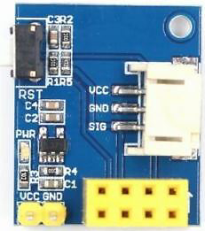
The ESP-0Controller 1S WS2812 RGB LED Adapter Module is a compact and efficient module designed to control WS2812 RGB LEDs. It integrates seamlessly with microcontrollers like the ESP8266 or ESP32, enabling users to create vibrant and dynamic lighting effects. This module simplifies the process of driving WS2812 LEDs by providing a stable power supply and signal conditioning, making it ideal for DIY projects, smart home lighting, and decorative displays.
Explore Projects Built with ESP-0Controller 1S WS2812 RGB LED Adapter Module


Explore Projects Built with ESP-0Controller 1S WS2812 RGB LED Adapter Module
Common Applications and Use Cases
- Addressable RGB LED strips for decorative lighting
- Smart home lighting systems
- Wearable electronics with RGB effects
- Interactive art installations
- Prototyping and testing WS2812 LED-based designs
Technical Specifications
Key Technical Details
- Input Voltage: 3.7V to 5.5V DC
- Output Signal: Digital signal for WS2812 LEDs
- Maximum Current: 1A (dependent on the power source and LED configuration)
- Supported LEDs: WS2812, WS2812B, and compatible addressable RGB LEDs
- Communication Protocol: Single-wire data protocol
- Dimensions: 25mm x 15mm x 5mm (approx.)
Pin Configuration and Descriptions
| Pin Name | Description |
|---|---|
| VIN | Power input pin (3.7V to 5.5V DC). Connect to the positive terminal of the power source. |
| GND | Ground pin. Connect to the negative terminal of the power source. |
| DIN | Data input pin. Connect to the microcontroller's data output pin. |
| DOUT | Data output pin. Connect to the data input of the first WS2812 LED. |
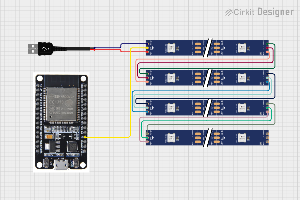
Usage Instructions
How to Use the Component in a Circuit
- Power the Module: Connect the VIN pin to a 3.7V-5.5V DC power source and the GND pin to ground.
- Connect the Microcontroller:
- Attach the microcontroller's data output pin to the DIN pin of the module.
- Ensure the microcontroller and the module share a common ground.
- Connect the LEDs:
- Link the DOUT pin of the module to the data input pin of the first WS2812 LED.
- Provide power to the WS2812 LEDs using the same power source as the module.
- Upload Code: Use a microcontroller (e.g., Arduino UNO, ESP8266, or ESP32) to send data signals to the module.
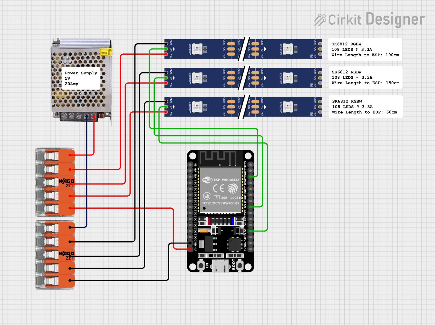
Important Considerations and Best Practices
- Ensure the power supply can handle the current requirements of the WS2812 LEDs.
- Use a capacitor (e.g., 1000µF, 6.3V or higher) across the power supply terminals to stabilize voltage.
- Add a 330Ω resistor between the microcontroller's data pin and the DIN pin to protect the LEDs from voltage spikes.
- Avoid powering too many LEDs directly from the module; use an external power source for large LED arrays.
Example Code for Arduino UNO
Below is an example code snippet to control WS2812 LEDs using the ESP-0Controller 1S module and the Adafruit NeoPixel library:
#include <Adafruit_NeoPixel.h>

// Define the pin connected to the DIN pin of the module
#define DATA_PIN 6

// Define the number of LEDs in the strip
#define NUM_LEDS 8

// Create a NeoPixel object
Adafruit_NeoPixel strip = Adafruit_NeoPixel(NUM_LEDS, DATA_PIN, NEO_GRB + NEO_KHZ800);

void setup() {
  strip.begin();  // Initialize the NeoPixel library
  strip.show();   // Turn off all LEDs initially
}

void loop() {
  // Example: Cycle through colors
  for (int i = 0; i < strip.numPixels(); i++) {
    strip.setPixelColor(i, strip.Color(255, 0, 0)); // Set to red
    strip.show();  // Update the LEDs
    delay(100);    // Wait 100ms
  }
}
Troubleshooting and FAQs
Common Issues and Solutions
LEDs Not Lighting Up:
- Verify the power supply voltage and current are sufficient for the LEDs.
- Check all connections, especially the DIN and DOUT pins.
- Ensure the microcontroller is correctly programmed and the data pin matches the code.
Flickering LEDs:
- Add a capacitor across the power supply terminals to reduce voltage fluctuations.
- Use a resistor (330Ω) between the microcontroller's data pin and the DIN pin.
Incorrect Colors:
- Confirm the LED type (e.g., WS2812) matches the library settings in the code.
- Ensure the data signal timing is correct (use a compatible library like Adafruit NeoPixel).
Module Overheating:
- Check for excessive current draw from the LEDs.
- Use an external power source for large LED arrays.
FAQs
Q: Can I use this module with a 12V power supply?
A: No, the module supports a maximum input voltage of 5.5V. Using a 12V supply will damage the module.
Q: How many LEDs can this module control?
A: The module can control hundreds of WS2812 LEDs, but ensure the power supply can handle the total current draw.
Q: Is this module compatible with other addressable LEDs?
A: This module is specifically designed for WS2812 and compatible LEDs. It may not work with other types like APA102 or SK6812.
Q: Do I need a level shifter for 3.3V microcontrollers?
A: In most cases, WS2812 LEDs can accept 3.3V data signals. However, for long data lines, a level shifter is recommended for reliable operation.