How to Use 32L4R9IDISCOVERY Board bottom view: Examples, Pinouts, and Specs
Introduction
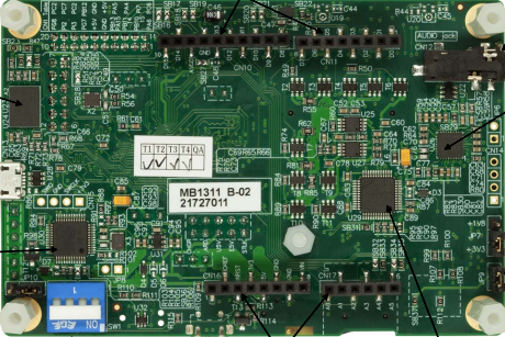
The 32L4R9IDISCOVERY board, manufactured by STMicroelectronics, is a development platform built around the STM32L4R9 microcontroller. This microcontroller is optimized for low-power applications, making the board ideal for energy-efficient embedded systems. The bottom view of the board reveals critical components, connectors, and power management features, which are essential for prototyping, debugging, and testing.
Explore Projects Built with 32L4R9IDISCOVERY Board bottom view


Explore Projects Built with 32L4R9IDISCOVERY Board bottom view
Common Applications and Use Cases
- Wearable devices and IoT applications
- Low-power data logging and sensing
- Prototyping for energy-efficient embedded systems
- Educational and research purposes in microcontroller programming
- Development of graphical user interfaces (GUIs) using the integrated display
Technical Specifications
Key Technical Details
- Microcontroller: STM32L4R9ZI (ARM Cortex-M4, 120 MHz, 2 MB Flash, 640 KB SRAM)
- Operating Voltage: 3.3V (regulated from USB or external power supply)
- Power Supply Options: USB, external 5V, or Li-Po battery
- Connectivity: USB Type-C, ST-LINK/V2-1 debugger/programmer
- Peripherals:
- 240x240 pixel TFT-LCD with capacitive touch
- MicroSD card slot
- Audio codec with microphone and headphone jack
- Dimensions: 95 mm x 65 mm
Pin Configuration and Descriptions
The bottom view of the 32L4R9IDISCOVERY board exposes several key connectors and pins. Below is a table summarizing the pin configuration:
| Pin/Connector | Description |
|---|---|
| CN7 | Arduino Uno V3-compatible headers for GPIO, ADC, PWM, and communication lines. |
| CN8 | Additional GPIO headers for extended functionality. |
| CN10 | STMod+ connector for external modules (e.g., sensors, RF modules). |
| CN12 | MicroSD card slot for data storage and logging. |
| CN13 | USB Type-C connector for power and data communication. |
| CN14 | Li-Po battery connector for portable applications. |
| JP1 | Jumper for selecting power source (USB, external, or battery). |
| JP2 | Jumper for enabling/disabling ST-LINK debugger. |
Usage Instructions
How to Use the Component in a Circuit
Powering the Board:
- Connect the USB Type-C cable to CN13 for powering the board and programming/debugging.
- Alternatively, connect a 5V external power supply to the VIN pin on CN7 or a Li-Po battery to CN14.
Programming the Microcontroller:
- Use the integrated ST-LINK/V2-1 debugger for programming and debugging via USB.
- Ensure JP2 is set to enable the ST-LINK functionality.
Interfacing with Peripherals:
- Use the Arduino-compatible headers (CN7) to connect external sensors, actuators, or shields.
- For additional peripherals, use the STMod+ connector (CN10) or GPIO headers (CN8).
Using the Display:
- The onboard TFT-LCD can be used for GUI development. Libraries such as TouchGFX or STM32Cube can simplify this process.
Data Logging:
- Insert a microSD card into CN12 for data storage. Use the STM32 HAL libraries to interface with the card.
Important Considerations and Best Practices
- Power Source Selection: Use JP1 to select the appropriate power source. Ensure only one power source is active at a time to avoid damage.
- Static Protection: Handle the board with care to avoid electrostatic discharge (ESD) damage.
- Firmware Updates: Regularly update the ST-LINK firmware and STM32CubeIDE to ensure compatibility with the latest features.
- Debugging: Disable the ST-LINK debugger (via JP2) when not in use to reduce power consumption.
Example Code for Arduino-Compatible GPIO
Below is an example of toggling an LED connected to a GPIO pin on the CN7 header using STM32 HAL libraries:
#include "stm32l4xx_hal.h"

// Define the GPIO pin for the LED
#define LED_PIN GPIO_PIN_5
#define LED_PORT GPIOA

void SystemClock_Config(void);
void GPIO_Init(void);

int main(void) {
    HAL_Init(); // Initialize the HAL library
    SystemClock_Config(); // Configure the system clock
    GPIO_Init(); // Initialize GPIO for the LED

    while (1) {
        HAL_GPIO_TogglePin(LED_PORT, LED_PIN); // Toggle the LED state
        HAL_Delay(500); // Wait for 500 ms
    }
}

void GPIO_Init(void) {
    __HAL_RCC_GPIOA_CLK_ENABLE(); // Enable clock for GPIOA

    GPIO_InitTypeDef GPIO_InitStruct = {0};
    GPIO_InitStruct.Pin = LED_PIN; // Configure the LED pin
    GPIO_InitStruct.Mode = GPIO_MODE_OUTPUT_PP; // Set as push-pull output
    GPIO_InitStruct.Pull = GPIO_NOPULL; // No pull-up or pull-down resistor
    GPIO_InitStruct.Speed = GPIO_SPEED_FREQ_LOW; // Low-speed operation
    HAL_GPIO_Init(LED_PORT, &GPIO_InitStruct); // Initialize the GPIO
}

void SystemClock_Config(void) {
    // System clock configuration code (auto-generated by STM32CubeMX)
}
Troubleshooting and FAQs
Common Issues and Solutions
Board Not Powering On:
- Ensure the USB cable is properly connected to CN13.
- Verify that JP1 is set to the correct power source.
- Check for any loose connections or damaged components.
Unable to Program the Microcontroller:
- Confirm that JP2 is set to enable the ST-LINK debugger.
- Ensure the ST-LINK drivers are installed on your computer.
- Verify that the STM32CubeIDE or other programming tools are correctly configured.
Peripherals Not Responding:
- Double-check the pin connections and ensure the correct GPIO pins are used.
- Verify that the peripheral initialization code is correct.
Display Not Working:
- Ensure the display is properly connected and powered.
- Use the appropriate libraries (e.g., TouchGFX) for GUI development.
FAQs
Can I use the board with an external debugger? Yes, you can connect an external debugger via the SWD pins on the CN7 header.
What is the maximum current draw for the board? The maximum current draw depends on the peripherals in use but typically does not exceed 500 mA when powered via USB.
Is the board compatible with Arduino libraries? While the board has Arduino-compatible headers, it requires STM32-specific libraries for programming.
Can I use the board for battery-powered applications? Yes, the board supports Li-Po batteries via CN14, making it suitable for portable applications.