How to Use ESP32 devBoard ver_d: Examples, Pinouts, and Specs
Introduction
The ESP32 devBoard ver_d, manufactured by Espressif (Part ID: ESP32d), is a versatile microcontroller development board designed for IoT applications and rapid prototyping. It features integrated Wi-Fi and Bluetooth capabilities, making it an excellent choice for wireless communication projects. With its powerful dual-core processor, ample GPIO pins, and support for various peripherals, the ESP32 devBoard ver_d is widely used in smart home devices, wearable electronics, industrial automation, and more.
Explore Projects Built with ESP32 devBoard ver_d


Explore Projects Built with ESP32 devBoard ver_d
Common Applications and Use Cases
- IoT (Internet of Things) devices and systems
- Home automation and smart appliances
- Wireless sensor networks
- Wearable technology
- Robotics and automation
- Prototyping for embedded systems
Technical Specifications
Key Technical Details
| Parameter | Specification |
|---|---|
| Microcontroller | ESP32 dual-core Xtensa LX6 processor |
| Clock Speed | Up to 240 MHz |
| Flash Memory | 4 MB (varies by model) |
| SRAM | 520 KB |
| Wireless Connectivity | Wi-Fi 802.11 b/g/n, Bluetooth 4.2 |
| Operating Voltage | 3.3V |
| Input Voltage (VIN) | 5V (via USB or external power supply) |
| GPIO Pins | 30+ (varies by board layout) |
| ADC Channels | 18 |
| DAC Channels | 2 |
| Communication Interfaces | UART, SPI, I2C, I2S, CAN, PWM |
| Power Consumption | ~160 mA (active), ~10 µA (deep sleep) |
| Dimensions | ~25.5 mm x 51 mm |
Pin Configuration and Descriptions
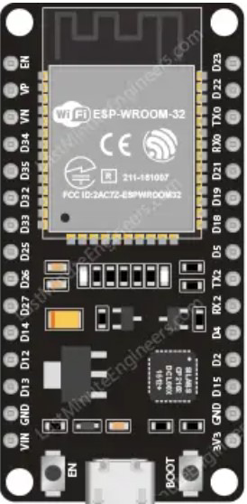
The ESP32 devBoard ver_d features a variety of pins for different functionalities. Below is a summary of the pin configuration:
| Pin Name | Functionality | Description |
|---|---|---|
| VIN | Power Input | Accepts 5V input from USB or external source. |
| 3V3 | Power Output | Provides 3.3V output for external components. |
| GND | Ground | Common ground for the circuit. |
| GPIO0 | General Purpose I/O, Boot Mode Select | Used for programming and boot mode selection. |
| GPIO2 | General Purpose I/O | Can be used for PWM, ADC, or other functions. |
| GPIO12 | General Purpose I/O | Supports ADC, PWM, and other functions. |
| GPIO13 | General Purpose I/O | Supports ADC, PWM, and other functions. |
| GPIO21 | General Purpose I/O | Commonly used for I2C SDA. |
| GPIO22 | General Purpose I/O | Commonly used for I2C SCL. |
| TX0 | UART Transmit | Serial communication TX pin. |
| RX0 | UART Receive | Serial communication RX pin. |
| EN | Enable | Resets the board when pulled low. |
Usage Instructions
How to Use the ESP32 devBoard ver_d in a Circuit
Powering the Board:
- Connect the board to a computer or USB power supply using a micro-USB cable.
- Alternatively, supply 5V to the VIN pin and connect GND to the ground of your power source.
Programming the Board:
- Install the Arduino IDE and add the ESP32 board support package.
- Select the correct board and port in the Arduino IDE.
- Write or upload your code to the board via the USB connection.
Connecting Peripherals:
- Use the GPIO pins to connect sensors, actuators, or other peripherals.
- Ensure that the voltage levels of connected devices are compatible with the ESP32 (3.3V logic).
Wireless Communication:
- Use the built-in Wi-Fi and Bluetooth modules for wireless communication.
- Configure the network settings in your code to connect to a Wi-Fi network or pair with Bluetooth devices.
Important Considerations and Best Practices
- Voltage Levels: The ESP32 operates at 3.3V logic. Avoid connecting 5V signals directly to GPIO pins to prevent damage.
- Boot Mode: Ensure GPIO0 is pulled low during programming to enter boot mode.
- Power Supply: Use a stable power source to avoid unexpected resets or malfunctions.
- Deep Sleep Mode: Utilize the deep sleep mode to reduce power consumption in battery-powered applications.
Example Code for Arduino UNO Integration
Below is an example of how to use the ESP32 devBoard ver_d to connect to a Wi-Fi network and send data to a server:
#include <WiFi.h> // Include the Wi-Fi library

// Replace with your network credentials
const char* ssid = "Your_SSID";
const char* password = "Your_PASSWORD";

void setup() {
  Serial.begin(115200); // Initialize serial communication
  delay(1000);

  // Connect to Wi-Fi
  Serial.print("Connecting to Wi-Fi");
  WiFi.begin(ssid, password);
  while (WiFi.status() != WL_CONNECTED) {
    delay(500);
    Serial.print(".");
  }
  Serial.println("\nWi-Fi connected!");
  Serial.print("IP Address: ");
  Serial.println(WiFi.localIP()); // Print the assigned IP address
}

void loop() {
  // Add your main code here
}
Troubleshooting and FAQs
Common Issues and Solutions
The board is not detected by the computer:
- Ensure the USB cable is functional and supports data transfer.
- Install the correct USB-to-serial driver for the ESP32.
Upload fails with a timeout error:
- Check that the correct board and port are selected in the Arduino IDE.
- Hold the BOOT button while uploading the code to enter programming mode.
Wi-Fi connection fails:
- Verify the SSID and password in your code.
- Ensure the Wi-Fi network is within range and operational.
GPIO pins not working as expected:
- Confirm that the pins are not being used for other functions (e.g., boot mode).
- Check for short circuits or incorrect wiring.
FAQs
Can the ESP32 devBoard ver_d operate on battery power?
Yes, you can power the board using a 3.7V LiPo battery connected to the appropriate pins, but ensure proper voltage regulation.What is the maximum number of devices that can connect via Bluetooth?
The ESP32 supports up to 7 simultaneous Bluetooth connections in classic mode.How do I reset the board?
Press the EN (Enable) button to reset the board.Can I use the ESP32 devBoard ver_d with MicroPython?
Yes, the ESP32 is compatible with MicroPython. You can flash the MicroPython firmware to the board and use it for development.
This concludes the documentation for the ESP32 devBoard ver_d. For further assistance, refer to the official Espressif documentation or community forums.