How to Use SparkFun PCA9306 Breakout: Examples, Pinouts, and Specs
Introduction
The SparkFun PCA9306 Breakout is a bi-directional I2C level shifter designed to facilitate communication between devices operating at different voltage levels. It supports voltage ranges from 1.8V to 5V, making it an ideal solution for interfacing 3.3V and 5V I2C devices. This breakout board is compact, easy to use, and highly reliable for voltage translation in I2C communication.
Explore Projects Built with SparkFun PCA9306 Breakout

Explore Projects Built with SparkFun PCA9306 Breakout
Common Applications and Use Cases
- Interfacing 3.3V microcontrollers (e.g., Arduino, ESP32) with 5V I2C peripherals.
- Bridging communication between sensors, displays, or modules operating at different voltage levels.
- Prototyping and testing circuits requiring I2C voltage level shifting.
- Enabling compatibility between legacy 5V devices and modern 3.3V systems.
Technical Specifications
Key Technical Details
| Parameter | Value |
|---|---|
| Voltage Range (VREF1) | 1.8V to 5V |
| Voltage Range (VREF2) | 1.8V to 5V |
| Maximum I2C Frequency | 400 kHz |
| Communication Protocol | I2C |
| Operating Temperature | -40°C to +85°C |
| Dimensions | 0.4" x 0.4" (10.16mm x 10.16mm) |
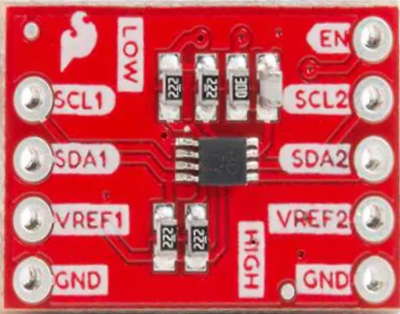
Pin Configuration and Descriptions
| Pin Name | Description |
|---|---|
| VREF1 | Reference voltage for the low-voltage side (1.8V to 5V). |
| VREF2 | Reference voltage for the high-voltage side (1.8V to 5V). |
| GND | Ground connection. |
| SCL1 | Low-voltage side I2C clock line. |
| SDA1 | Low-voltage side I2C data line. |
| SCL2 | High-voltage side I2C clock line. |
| SDA2 | High-voltage side I2C data line. |
Usage Instructions
How to Use the Component in a Circuit
Power Connections:
- Connect the low-voltage reference (e.g., 3.3V) to the
VREF1pin. - Connect the high-voltage reference (e.g., 5V) to the
VREF2pin. - Connect the
GNDpin to the ground of your circuit.
- Connect the low-voltage reference (e.g., 3.3V) to the
I2C Connections:
- Connect the low-voltage I2C lines (
SCL1andSDA1) to the I2C pins of your low-voltage device (e.g., microcontroller). - Connect the high-voltage I2C lines (
SCL2andSDA2) to the I2C pins of your high-voltage device (e.g., sensor or module).
- Connect the low-voltage I2C lines (
Pull-Up Resistors:
- Ensure that appropriate pull-up resistors are present on both the low-voltage and high-voltage sides of the I2C bus. Typical values range from 4.7kΩ to 10kΩ, depending on the bus capacitance and speed.
Verify Connections:
- Double-check all connections to ensure proper voltage levels and avoid damage to the devices.
Important Considerations and Best Practices
- Voltage Compatibility: Ensure that the voltage levels on
VREF1andVREF2match the operating voltages of the connected devices. - I2C Speed: The PCA9306 supports I2C speeds up to 400 kHz. Ensure that your devices are configured to operate within this limit.
- Pull-Up Resistors: If your devices already have pull-up resistors, additional resistors may not be necessary. Avoid excessive pull-up strength, as it can cause communication issues.
- Signal Integrity: Keep I2C lines as short as possible to minimize noise and signal degradation.
Example: Using with Arduino UNO
Below is an example of connecting the SparkFun PCA9306 Breakout to an Arduino UNO and a 5V I2C sensor.
Circuit Diagram
VREF1→ 3.3V (Arduino UNO 3.3V pin)VREF2→ 5V (Arduino UNO 5V pin)GND→ GND (common ground)SCL1→ A5 (Arduino I2C clock pin)SDA1→ A4 (Arduino I2C data pin)SCL2→ SCL pin of the 5V sensorSDA2→ SDA pin of the 5V sensor
Arduino Code Example
#include <Wire.h> // Include the Wire library for I2C communication

void setup() {
  Wire.begin(); // Initialize I2C communication
  Serial.begin(9600); // Start serial communication for debugging

  // Example: Communicate with a 5V I2C sensor
  Wire.beginTransmission(0x40); // Replace 0x40 with your sensor's I2C address
  Wire.write(0x00); // Example: Write a command to the sensor
  Wire.endTransmission();

  Serial.println("I2C communication initialized.");
}

void loop() {
  Wire.requestFrom(0x40, 2); // Request 2 bytes from the sensor
  if (Wire.available() == 2) {
    int data = Wire.read() << 8 | Wire.read(); // Read and combine two bytes
    Serial.print("Sensor Data: ");
    Serial.println(data);
  }
  delay(1000); // Wait 1 second before the next request
}
Troubleshooting and FAQs
Common Issues and Solutions
No Communication Between Devices:
- Verify that
VREF1andVREF2are connected to the correct voltage levels. - Check for proper pull-up resistors on both sides of the I2C bus.
- Ensure that the I2C addresses of the devices are correct and do not conflict.
- Verify that
Data Corruption or Noise:
- Shorten the I2C lines to reduce noise.
- Use appropriate pull-up resistor values (e.g., 4.7kΩ to 10kΩ).
- Check for loose or faulty connections.
Overheating or Damage:
- Ensure that the voltage levels on
VREF1andVREF2do not exceed the specified range (1.8V to 5V). - Avoid connecting devices with incompatible voltage levels.
- Ensure that the voltage levels on
FAQs
Q: Can the PCA9306 be used for SPI communication?
A: No, the PCA9306 is specifically designed for I2C communication and does not support SPI.
Q: Do I need pull-up resistors on both sides of the level shifter?
A: Yes, pull-up resistors are required on both the low-voltage and high-voltage sides of the I2C bus for proper operation.
Q: What is the maximum I2C speed supported by the PCA9306?
A: The PCA9306 supports I2C speeds up to 400 kHz.
This documentation provides a comprehensive guide to using the SparkFun PCA9306 Breakout for I2C level shifting. By following the instructions and best practices outlined above, you can ensure reliable and efficient communication between devices operating at different voltage levels.