
How to Use ATmega644 (PDIP-40): Examples, Pinouts, and Specs

 Design with ATmega644 (PDIP-40) in Cirkit Designer
Introduction
The ATmega644 is a high-performance 8-bit microcontroller from Atmel's AVR family. It features 64KB of flash memory, 4KB of SRAM, and 2KB of EEPROM, making it suitable for a wide range of embedded applications. With 32 general-purpose I/O pins, a rich set of peripherals, and support for in-system programming, the ATmega644 is ideal for applications such as home automation, robotics, industrial control systems, and custom electronics projects.
Explore Projects Built with ATmega644 (PDIP-40)
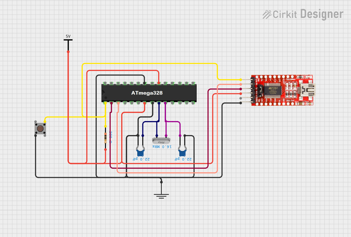 Open Project in Cirkit Designer
 Open Project in Cirkit Designer
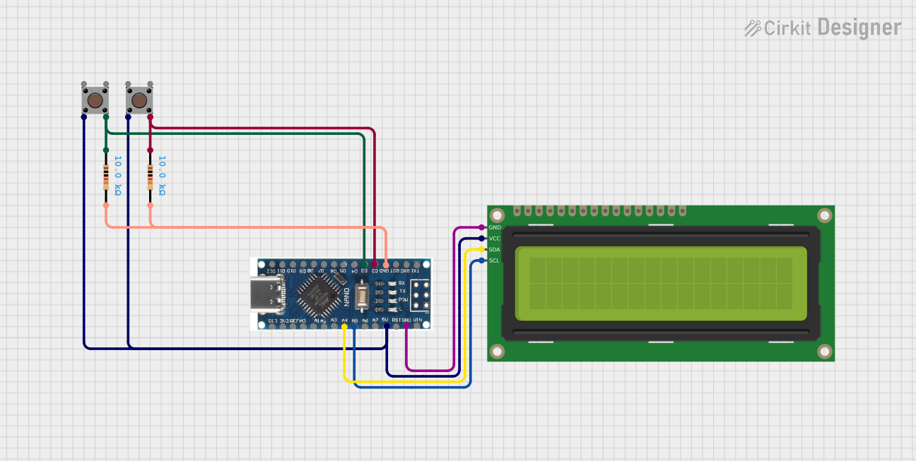 Open Project in Cirkit Designer
 Open Project in Cirkit Designer
Explore Projects Built with ATmega644 (PDIP-40)
Open Project in Cirkit DesignerOpen Project in Cirkit DesignerOpen Project in Cirkit DesignerOpen Project in Cirkit DesignerCommon Applications
- Embedded systems and IoT devices
- Robotics and motor control
- Data acquisition and processing
- Home automation and smart devices
- Educational and prototyping projects
Technical Specifications
Key Technical Details
| Parameter | Value |
|---|---|
| Architecture | 8-bit AVR RISC |
| Flash Memory | 64KB |
| SRAM | 4KB |
| EEPROM | 2KB |
| Operating Voltage | 2.7V - 5.5V |
| Maximum Clock Frequency | 20 MHz |
| I/O Pins | 32 |
| Timers | 3 (Two 8-bit, One 16-bit) |
| ADC Resolution | 10-bit (8 channels) |
| Communication Interfaces | UART, SPI, I2C (TWI) |
| Package Type | PDIP-40 |
Pin Configuration and Descriptions
The ATmega644 in the PDIP-40 package has 40 pins. Below is the pin configuration:
| Pin Number | Pin Name | Description |
|---|---|---|
| 1 | PA0 | ADC0/PCINT0 (Analog Input/Pin Change Interrupt) |
| 2 | PA1 | ADC1/PCINT1 |
| 3 | PA2 | ADC2/PCINT2 |
| 4 | PA3 | ADC3/PCINT3 |
| 5 | PA4 | ADC4/PCINT4 |
| 6 | PA5 | ADC5/PCINT5 |
| 7 | PA6 | ADC6/PCINT6 |
| 8 | PA7 | ADC7/PCINT7 |
| 9 | AREF | Analog Reference Voltage |
| 10 | GND | Ground |
| 11 | AVCC | Analog Power Supply |
| 12 | PC0 | PCINT8/SCL (I2C Clock Line) |
| 13 | PC1 | PCINT9/SDA (I2C Data Line) |
| 14 | PC2 | PCINT10 |
| 15 | PC3 | PCINT11 |
| 16 | PC4 | PCINT12 |
| 17 | PC5 | PCINT13 |
| 18 | PC6 | PCINT14/RESET |
| 19 | PC7 | PCINT15 |
| 20 | VCC | Power Supply |
| 21 | GND | Ground |
| 22 | PB0 | PCINT16/ICP1 (Input Capture Pin) |
| 23 | PB1 | PCINT17/OC1A (Timer Output Compare A) |
| 24 | PB2 | PCINT18/OC1B (Timer Output Compare B) |
| 25 | PB3 | PCINT19/MOSI (SPI Master Out Slave In) |
| 26 | PB4 | PCINT20/MISO (SPI Master In Slave Out) |
| 27 | PB5 | PCINT21/SCK (SPI Clock) |
| 28 | PB6 | PCINT22/XTAL1 (Crystal Oscillator Input) |
| 29 | PB7 | PCINT23/XTAL2 (Crystal Oscillator Output) |
| 30 | PD0 | PCINT24/RXD (UART Receive) |
| 31 | PD1 | PCINT25/TXD (UART Transmit) |
| 32 | PD2 | PCINT26/INT0 (External Interrupt 0) |
| 33 | PD3 | PCINT27/INT1 (External Interrupt 1) |
| 34 | PD4 | PCINT28/T0 (Timer/Counter 0 External Clock) |
| 35 | PD5 | PCINT29/T1 (Timer/Counter 1 External Clock) |
| 36 | PD6 | PCINT30/OC0A (Timer Output Compare A) |
| 37 | PD7 | PCINT31/OC0B (Timer Output Compare B) |
| 38 | RESET | Reset Pin |
| 39 | XTAL1 | Crystal Oscillator Input |
| 40 | XTAL2 | Crystal Oscillator Output |
Usage Instructions
How to Use the ATmega644 in a Circuit
- Power Supply: Connect the VCC pin to a 5V power source and the GND pins to ground. Ensure proper decoupling capacitors (e.g., 0.1µF) are placed near the power pins to reduce noise.
- Clock Source: Use an external crystal oscillator (e.g., 16 MHz) connected to the XTAL1 and XTAL2 pins, along with appropriate capacitors (e.g., 22pF).
- Programming: Use an ISP (In-System Programmer) to program the microcontroller via the SPI pins (MOSI, MISO, SCK, and RESET).
- I/O Pins: Configure the 32 general-purpose I/O pins as input or output in your firmware. Use pull-up resistors for input pins if needed.
- Peripherals: Utilize the built-in peripherals such as UART, SPI, I2C, and ADC for communication and data acquisition.
Important Considerations
- Voltage Levels: Ensure all connected devices operate within the ATmega644's voltage range (2.7V - 5.5V).
- Reset Pin: The RESET pin must be pulled high with a resistor (e.g., 10kΩ) to prevent accidental resets.
- Unused Pins: Configure unused pins as inputs with pull-up resistors or outputs to avoid floating states.
- Heat Dissipation: Ensure proper ventilation or heat sinking if the microcontroller operates at high frequencies or under heavy load.
Example: Interfacing with Arduino UNO
The ATmega644 can be programmed using the Arduino IDE by adding the appropriate board definitions. Below is an example of blinking an LED connected to pin PB0:
// Define the LED pin
#define LED_PIN 8  // PB0 corresponds to digital pin 8 in Arduino IDE

void setup() {
  pinMode(LED_PIN, OUTPUT);  // Set PB0 as an output
}

void loop() {
  digitalWrite(LED_PIN, HIGH);  // Turn the LED on
  delay(1000);                  // Wait for 1 second
  digitalWrite(LED_PIN, LOW);   // Turn the LED off
  delay(1000);                  // Wait for 1 second
}
Troubleshooting and FAQs
Common Issues
Microcontroller Not Responding:
- Cause: Incorrect power supply or missing decoupling capacitors.
- Solution: Verify the power connections and add 0.1µF capacitors near the VCC and GND pins.
Programming Failure:
- Cause: Incorrect ISP connections or incompatible programmer.
- Solution: Double-check the SPI pin connections and ensure the programmer supports ATmega644.
Unstable Operation:
- Cause: Missing or incorrect clock source.
- Solution: Ensure the crystal oscillator and capacitors are properly connected to XTAL1 and XTAL2.
Floating Pins:
- Cause: Unused pins left unconnected.
- Solution: Configure unused pins as inputs with pull-up resistors or as outputs.
FAQs
Q: Can the ATmega644 run at 3.3V?
A: Yes, the ATmega644 can operate at 3.3V, but the maximum clock frequency will be limited to 10 MHz.
Q: How do I enable the internal pull-up resistors?
A: Set the pin as an input and write a HIGH value to it in your firmware. For example:
pinMode(pin, INPUT);
digitalWrite(pin, HIGH);  // Enable pull-up resistor
Q: Can I use the ATmega644 without an external crystal?
A: Yes, the ATmega644 has an internal 8 MHz RC oscillator, but it may not be as accurate as an external crystal.