Cirkit Designer Logo
Cirkit Designer
Your all-in-one circuit design IDE
Home / 
Component Documentation

How to Use 1 gang socket: Examples, Pinouts, and Specs

Image of 1 gang socket
Cirkit Designer LogoDesign with 1 gang socket in Cirkit Designer

Introduction

  • The 1 gang socket is a single outlet socket designed to connect one electrical device to the power supply. It is commonly used in residential, commercial, and industrial settings to provide a reliable and safe connection to mains electricity.
  • Typical applications include powering household appliances, office equipment, and other electrical devices. It is a fundamental component in electrical installations and is often mounted on walls or integrated into extension cords.

Explore Projects Built with 1 gang socket

Use Cirkit Designer to design, explore, and prototype these projects online. Some projects support real-time simulation. Click "Open Project" to start designing instantly!
Toggle Switch Controlled Lamp Circuit with Banana Sockets
Image of STAIRCASE: A project utilizing 1 gang socket in a practical application
This circuit consists of two toggle switches and a red lamp connected to panel mount banana sockets. The switches control the connection between the red and black banana sockets, allowing the lamp to be turned on or off depending on the switch positions.
Cirkit Designer LogoOpen Project in Cirkit Designer
Heater Control Circuit with Power Socket Integration
Image of Simple Water Heater: A project utilizing 1 gang socket in a practical application
The circuit connects a heater to a power source via a socket. The heater is likely to be powered directly from the socket, with the positive and negative terminals of the socket providing the necessary voltage and ground connections to the heater. There are no control elements or sensors present in the circuit, indicating that the heater operates at a constant power level when connected.
Cirkit Designer LogoOpen Project in Cirkit Designer
AND Gate Circuit with LED Indicator and Banana Socket Inputs
Image of dayra: A project utilizing 1 gang socket in a practical application
This circuit features a 4081 quad 2-input AND gate IC connected to two red panel mount banana sockets as inputs and a black panel mount banana socket as an output. The circuit also includes an LED connected to ground, and the entire setup is powered by a Vcc source.
Cirkit Designer LogoOpen Project in Cirkit Designer
Dual 5V Power Supply Distribution Circuit with Toggle Switch Control
Image of rfdriver: A project utilizing 1 gang socket in a practical application
This circuit consists of two 5V 5A power supplies connected to an AC wall plug point, providing DC output through a 12-way connector. The ground connections from both power supplies are interconnected and also connected to the ground pins of two toggle switches. The DC outputs from the power supplies are separately connected to different pins on the 12-way connector, with each power supply output being switchable via one of the toggle switches.
Cirkit Designer LogoOpen Project in Cirkit Designer

Explore Projects Built with 1 gang socket

Use Cirkit Designer to design, explore, and prototype these projects online. Some projects support real-time simulation. Click "Open Project" to start designing instantly!
Image of STAIRCASE: A project utilizing 1 gang socket in a practical application
Toggle Switch Controlled Lamp Circuit with Banana Sockets
This circuit consists of two toggle switches and a red lamp connected to panel mount banana sockets. The switches control the connection between the red and black banana sockets, allowing the lamp to be turned on or off depending on the switch positions.
Cirkit Designer LogoOpen Project in Cirkit Designer
Image of Simple Water Heater: A project utilizing 1 gang socket in a practical application
Heater Control Circuit with Power Socket Integration
The circuit connects a heater to a power source via a socket. The heater is likely to be powered directly from the socket, with the positive and negative terminals of the socket providing the necessary voltage and ground connections to the heater. There are no control elements or sensors present in the circuit, indicating that the heater operates at a constant power level when connected.
Cirkit Designer LogoOpen Project in Cirkit Designer
Image of dayra: A project utilizing 1 gang socket in a practical application
AND Gate Circuit with LED Indicator and Banana Socket Inputs
This circuit features a 4081 quad 2-input AND gate IC connected to two red panel mount banana sockets as inputs and a black panel mount banana socket as an output. The circuit also includes an LED connected to ground, and the entire setup is powered by a Vcc source.
Cirkit Designer LogoOpen Project in Cirkit Designer
Image of rfdriver: A project utilizing 1 gang socket in a practical application
Dual 5V Power Supply Distribution Circuit with Toggle Switch Control
This circuit consists of two 5V 5A power supplies connected to an AC wall plug point, providing DC output through a 12-way connector. The ground connections from both power supplies are interconnected and also connected to the ground pins of two toggle switches. The DC outputs from the power supplies are separately connected to different pins on the 12-way connector, with each power supply output being switchable via one of the toggle switches.
Cirkit Designer LogoOpen Project in Cirkit Designer

Technical Specifications

  • Voltage Rating: 220-250V AC (varies by region)
  • Current Rating: 10A or 13A (depending on the model)
  • Frequency: 50Hz or 60Hz
  • Material: Flame-retardant plastic housing with brass or copper internal contacts
  • Mounting Type: Surface-mounted or flush-mounted
  • Dimensions: Standard sizes vary by region (e.g., 86mm x 86mm for UK models)
  • Safety Features: May include shutters for child safety, grounding pin, and surge protection (optional)

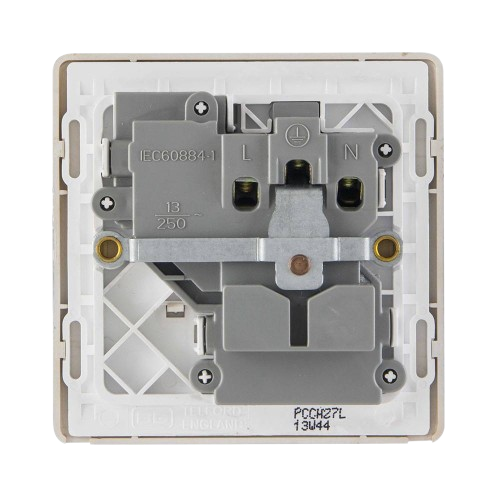
Pin Configuration and Descriptions

The 1 gang socket typically has three terminals for wiring:

Terminal Name Description Wire Connection Type
Live (L) Connects to the live/hot wire Brown (or Red)
Neutral (N) Connects to the neutral wire Blue (or Black)
Earth (E) Connects to the ground/earth wire Green/Yellow

Note: Wire color codes may vary by country. Always follow local electrical standards.

Usage Instructions

  1. Installation:

    • Ensure the power supply is turned off before installation.
    • Mount the socket securely on the wall or desired surface using screws.
    • Connect the wires to the appropriate terminals (Live, Neutral, Earth) as per the pin configuration table above.
    • Tighten the terminal screws to ensure a secure connection.
    • Replace the socket cover and secure it with screws.
  2. Important Considerations:

    • Always use wires of appropriate gauge to handle the rated current.
    • Ensure proper grounding to prevent electrical hazards.
    • Avoid overloading the socket by connecting devices that exceed the rated current.
    • Use a voltage tester to confirm the absence of power before handling the socket.
  3. Best Practices:

    • Periodically inspect the socket for signs of wear, damage, or overheating.
    • Use sockets with built-in surge protection in areas prone to voltage spikes.
    • For outdoor installations, use weatherproof sockets to protect against moisture.
  4. Arduino UNO Integration: While the 1 gang socket is not directly compatible with low-voltage microcontrollers like the Arduino UNO, it can be controlled indirectly using a relay module. Below is an example of how to control a device connected to a 1 gang socket using an Arduino and a relay:

/*
  Example: Controlling a 1 Gang Socket with Arduino and Relay
  This code toggles a relay to control a device connected to the socket.
  WARNING: Ensure proper isolation between high-voltage and low-voltage circuits.
*/

const int relayPin = 7; // Pin connected to the relay module

void setup() {
  pinMode(relayPin, OUTPUT); // Set relay pin as output
  digitalWrite(relayPin, LOW); // Ensure relay is off initially
}

void loop() {
  digitalWrite(relayPin, HIGH); // Turn on the relay (socket powered)
  delay(5000); // Keep the socket powered for 5 seconds
  digitalWrite(relayPin, LOW); // Turn off the relay (socket off)
  delay(5000); // Wait for 5 seconds before repeating
}

Warning: High-voltage wiring should only be handled by qualified personnel. Always use a relay module with proper isolation to control mains power.

Troubleshooting and FAQs

Common Issues

  1. Socket not providing power:

    • Cause: Loose wiring or damaged internal components.
    • Solution: Turn off the power supply, inspect the wiring, and ensure all connections are secure. Replace the socket if necessary.
  2. Overheating socket:

    • Cause: Overloading or poor contact between the plug and socket.
    • Solution: Reduce the load on the socket and ensure the plug fits snugly. Replace the socket if overheating persists.
  3. Device not turning on when controlled via Arduino:

    • Cause: Incorrect relay wiring or insufficient power to the relay module.
    • Solution: Verify the relay connections and ensure the Arduino provides sufficient current to activate the relay.

FAQs

  • Can I use a 1 gang socket outdoors?

    • Yes, but only if it is a weatherproof model designed for outdoor use.
  • What is the difference between a 1 gang and 2 gang socket?

    • A 1 gang socket has a single outlet, while a 2 gang socket has two outlets.
  • Can I install a 1 gang socket myself?

    • Yes, if you have basic electrical knowledge and follow safety guidelines. Otherwise, hire a licensed electrician.
  • Is surge protection included in all 1 gang sockets?

    • No, surge protection is an optional feature. Check the product specifications before purchasing.