How to Use HV826MG_BACKLIGHT: Examples, Pinouts, and Specs
Introduction
The HV826MG_BACKLIGHT is a high-voltage boost converter optimized for driving white LED backlights in LCD panels. It is capable of converting a low-voltage input into a high-voltage output necessary for illuminating the backlight. Due to its efficiency and compact form factor, the HV826MG_BACKLIGHT is particularly suitable for use in portable electronic devices where space and power consumption are critical considerations.
Explore Projects Built with HV826MG_BACKLIGHT

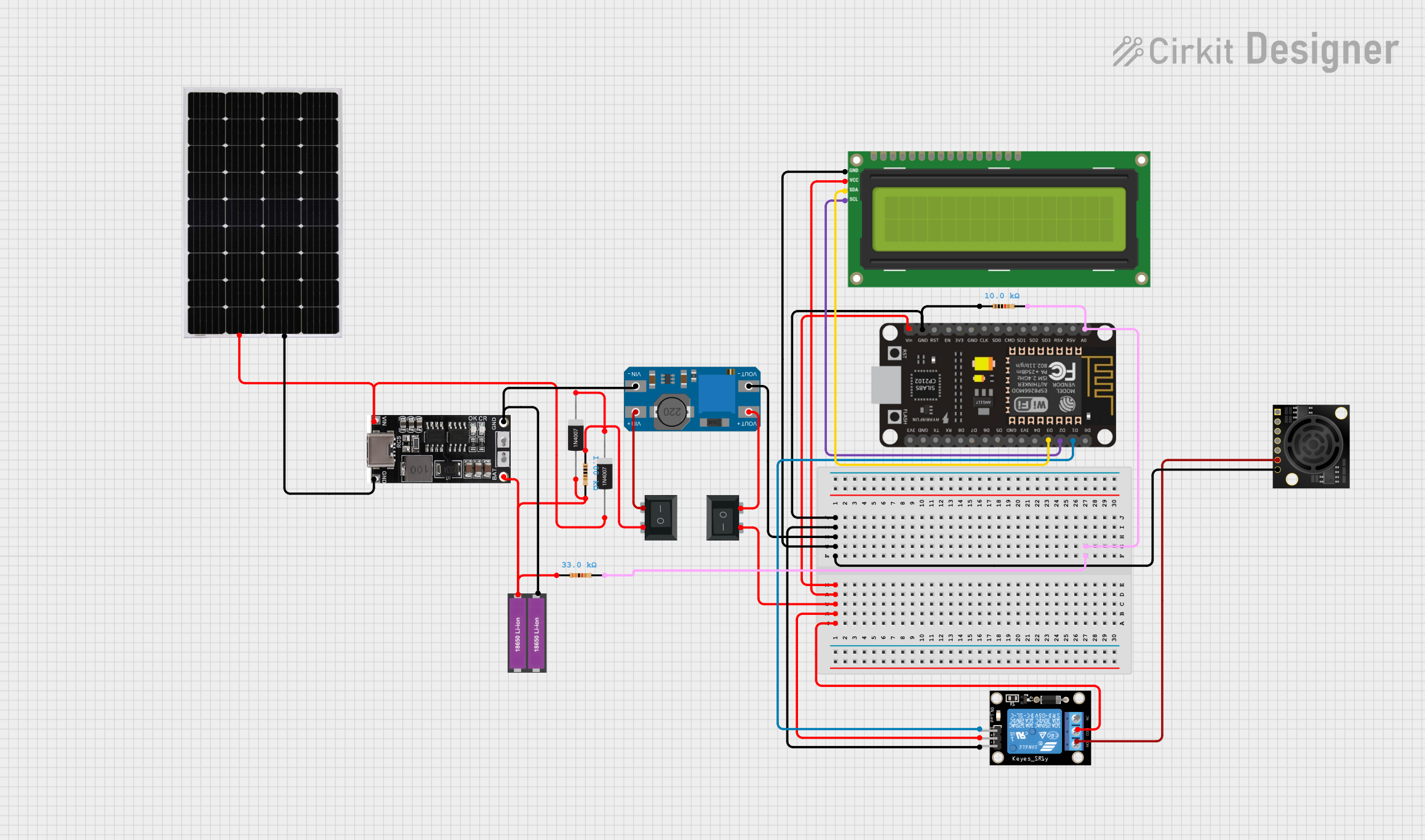

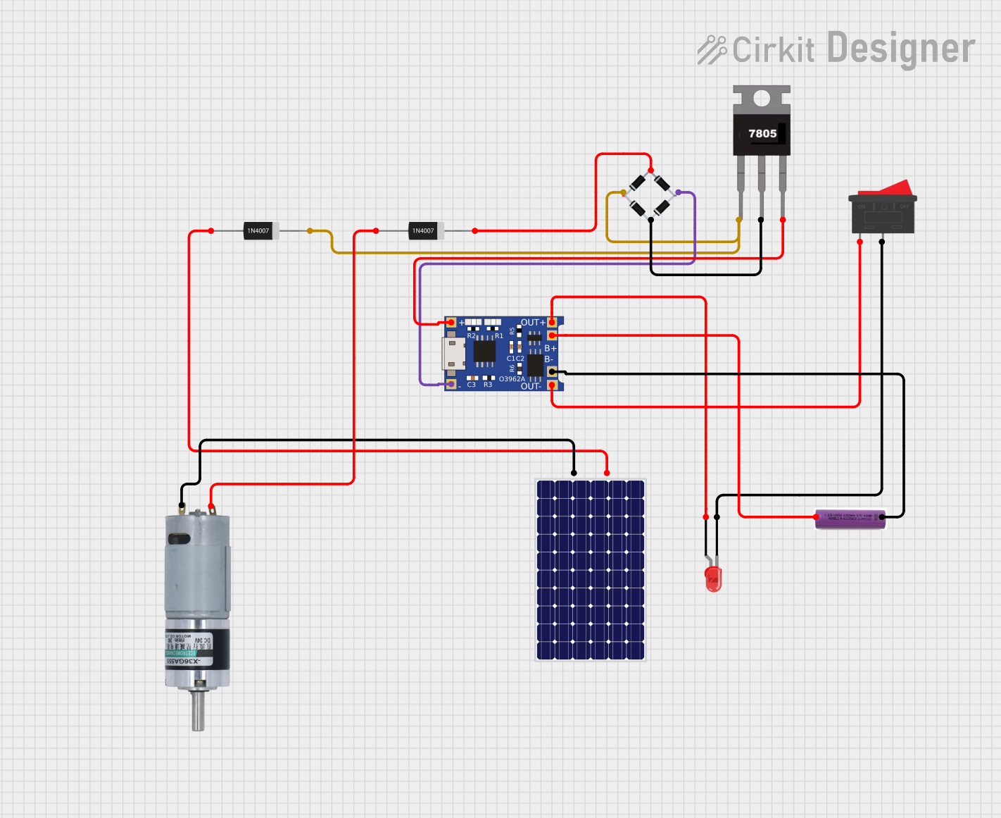
Explore Projects Built with HV826MG_BACKLIGHT
Common Applications and Use Cases
- Laptop and notebook computers
- Portable media players
- Handheld gaming devices
- GPS units
- Other devices with LCD screens requiring backlighting
Technical Specifications
Key Technical Details
- Input Voltage Range: 2.4V to 5.5V
- Output Voltage Range: Up to 28V
- Maximum Output Current: 30mA
- Switching Frequency: 1.2MHz
- Efficiency: Up to 85%
- Operating Temperature Range: -40°C to +85°C
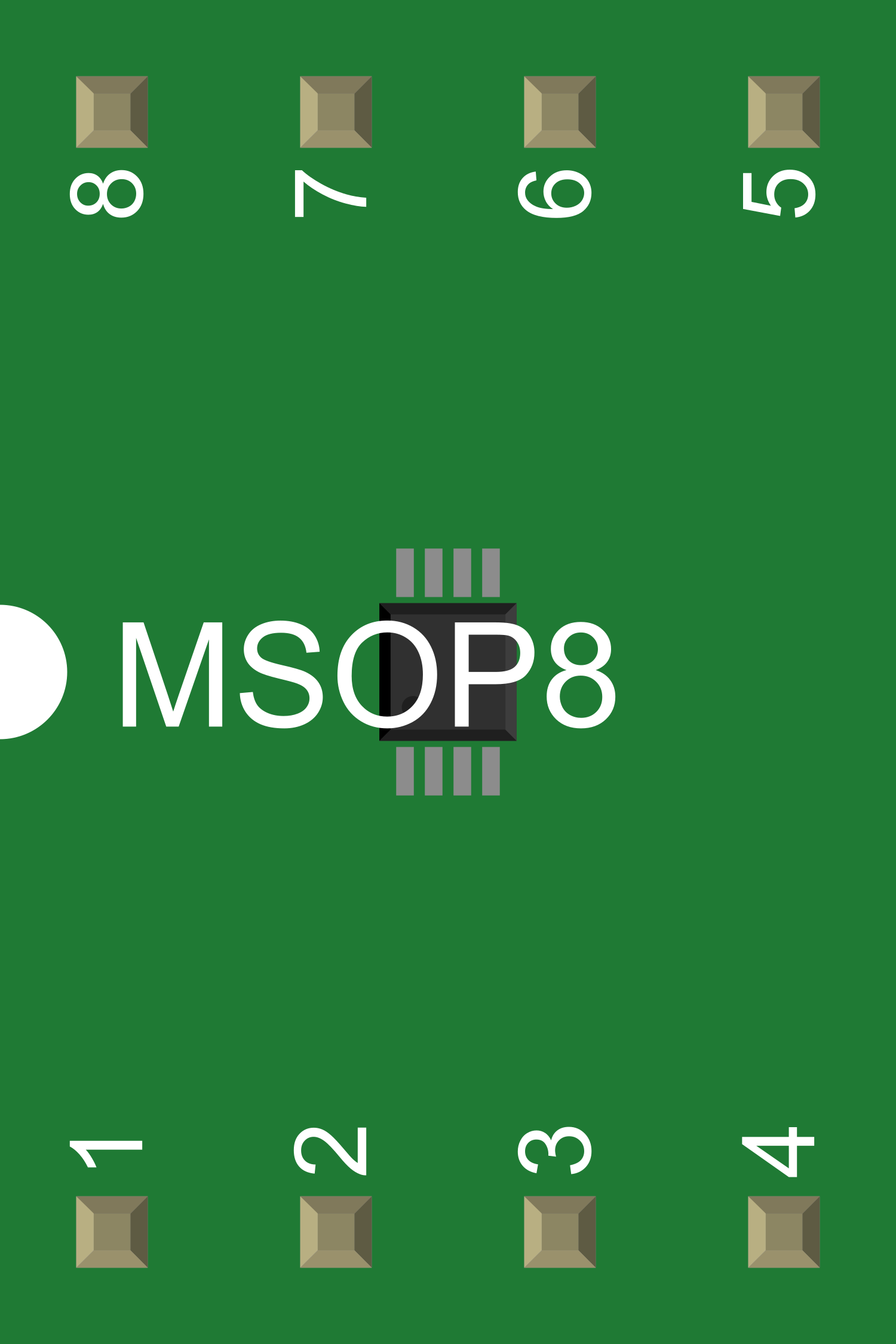
Pin Configuration and Descriptions
| Pin Number | Name | Description |
|---|---|---|
| 1 | VIN | Input voltage supply pin. Connect to a 2.4V to 5.5V power source. |
| 2 | GND | Ground pin. Connect to the system ground. |
| 3 | SW | Switch pin. Connects to the inductor and diode for the boost converter. |
| 4 | FB | Feedback pin. Connects to the voltage divider for output voltage regulation. |
| 5 | EN | Enable pin. A logic high enables the device, while a logic low disables it. |
| 6 | LX | Inductor connection pin. Connects to the inductor and output capacitor. |
Usage Instructions
How to Use the Component in a Circuit
- Power Supply Connection: Connect a power source within the specified input voltage range to the VIN pin and connect the GND pin to the system ground.
- Inductor Selection: Choose an appropriate inductor value as per the datasheet recommendations and connect it between the SW and LX pins.
- Output Capacitor: Connect an output capacitor between the LX pin and GND to stabilize the output voltage.
- Feedback Network: Create a voltage divider using two resistors connected between the LX pin, FB pin, and GND to set the desired output voltage.
- Enable Pin: Control the operation of the HV826MG_BACKLIGHT by applying a logic high or low signal to the EN pin.
Important Considerations and Best Practices
- Ensure that the input voltage does not exceed the maximum rating to prevent damage to the device.
- Use ceramic capacitors with low equivalent series resistance (ESR) for better performance.
- Place the inductor and capacitors as close to the device as possible to minimize losses and noise.
- Avoid long traces on the PCB to reduce electromagnetic interference (EMI).
- Implement proper thermal management if the device is expected to operate at high ambient temperatures or output currents.
Troubleshooting and FAQs
Common Issues Users Might Face
- Insufficient Brightness: Check if the output voltage is within the specified range and adjust the feedback network if necessary.
- Device Overheating: Ensure that the input voltage is within limits and that the thermal management is adequate.
- Intermittent Operation: Verify that the EN pin is receiving a stable logic signal and that there are no loose connections in the circuit.
Solutions and Tips for Troubleshooting
- If the output voltage is too low, re-evaluate the resistor values in the feedback network.
- For overheating issues, consider adding a heatsink or improving airflow around the device.
- Ensure that the power supply can provide sufficient current for the startup and operation of the boost converter.
FAQs
Q: Can the HV826MG_BACKLIGHT drive multiple LEDs in series? A: Yes, as long as the total forward voltage of the LEDs does not exceed the maximum output voltage of the device.
Q: Is it possible to adjust the output voltage? A: Yes, the output voltage can be adjusted by changing the resistor values in the feedback network.
Q: What is the maximum number of LEDs that can be driven by this device? A: The maximum number is determined by the forward voltage of the LEDs and the maximum output current of the HV826MG_BACKLIGHT. Ensure the total forward voltage and current do not exceed the specifications.
Q: How do I enable or disable the HV826MG_BACKLIGHT? A: Apply a logic high signal to the EN pin to enable the device, and a logic low signal to disable it.
Q: What should I do if the device is not starting up? A: Check the connections to the VIN, GND, and EN pins for proper voltage levels and signal integrity. Also, verify the inductor and capacitor values and placements.
Example Arduino UNO Connection and Code
// Define the Arduino pin connected to the HV826MG_BACKLIGHT's EN pin
#define ENABLE_PIN 7

void setup() {
  pinMode(ENABLE_PIN, OUTPUT);
  // Start with the backlight disabled
  digitalWrite(ENABLE_PIN, LOW);
}

void loop() {
  // Enable the HV826MG_BACKLIGHT
  digitalWrite(ENABLE_PIN, HIGH);
  delay(5000); // Keep the backlight on for 5 seconds

  // Disable the HV826MG_BACKLIGHT
  digitalWrite(ENABLE_PIN, LOW);
  delay(5000); // Keep the backlight off for 5 seconds
}
Note: This example assumes that the HV826MG_BACKLIGHT is properly connected to the Arduino UNO with the EN pin connected to digital pin 7. The code toggles the backlight on and off every 5 seconds. Ensure that the Arduino's output voltage is compatible with the HV826MG_BACKLIGHT's input voltage requirements.