How to Use BD139: Examples, Pinouts, and Specs
Introduction
The BD139 is a general-purpose NPN bipolar junction transistor (BJT) designed for amplification and switching applications. With a maximum collector current of 1.5A and a maximum collector-emitter voltage of 80V, the BD139 is a versatile component suitable for a wide range of electronic circuits. Its robust design and reliable performance make it a popular choice for hobbyists and professionals alike.
Explore Projects Built with BD139

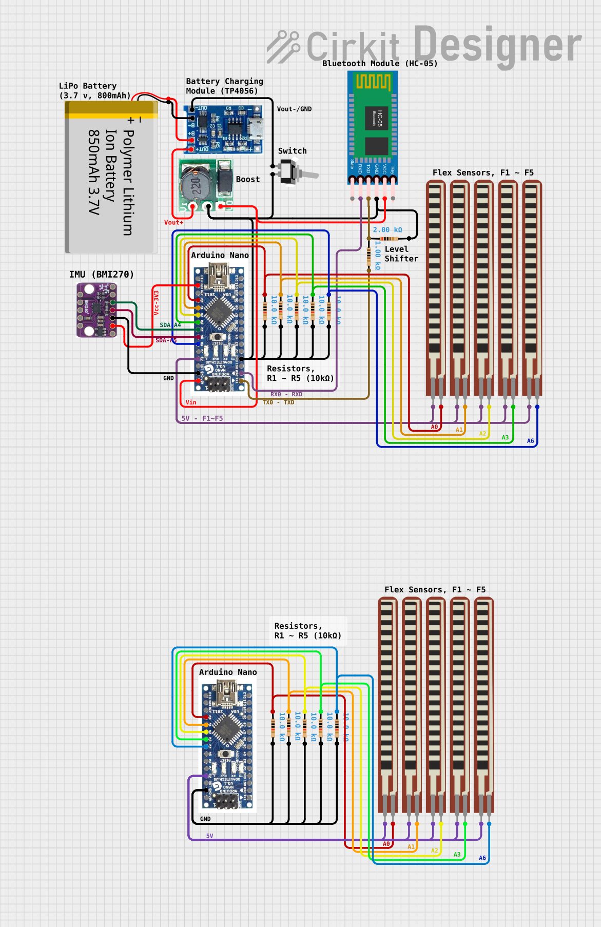


Explore Projects Built with BD139
Common Applications
- Audio amplification circuits
- Motor control and driver circuits
- Signal processing
- Power regulation and switching
- General-purpose electronic projects
Technical Specifications
The BD139 transistor has the following key technical details:
| Parameter | Value |
|---|---|
| Transistor Type | NPN |
| Maximum Collector Current (Ic) | 1.5A |
| Maximum Collector-Emitter Voltage (Vce) | 80V |
| Maximum Collector-Base Voltage (Vcb) | 100V |
| Maximum Emitter-Base Voltage (Veb) | 5V |
| Maximum Power Dissipation (Pd) | 12.5W |
| DC Current Gain (hFE) | 25 to 250 (depending on Ic) |
| Transition Frequency (fT) | 190 MHz |
| Package Type | TO-126 |
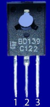
Pin Configuration
The BD139 transistor has three pins: Base (B), Collector (C), and Emitter (E). The pinout is as follows:
| Pin Number | Pin Name | Description |
|---|---|---|
| 1 | Emitter (E) | Current flows out of this pin |
| 2 | Collector (C) | Current flows into this pin |
| 3 | Base (B) | Controls the transistor's operation |
The pin layout for the BD139 in the TO-126 package is shown below (viewed from the front, with the flat side facing you):
   _______
  |       |
  |       |
  |_______|
   | | |
   E C B
Usage Instructions
Using the BD139 in a Circuit
The BD139 can be used in both switching and amplification configurations. Below are the general steps for using the BD139 in a circuit:
Determine the Operating Mode:
- For switching: Use the transistor as an electronic switch by applying a suitable base current to turn it on or off.
- For amplification: Use the transistor in a common-emitter configuration to amplify input signals.
Base Resistor Selection:
- To protect the transistor, calculate the base resistor value using the formula: [ R_b = \frac{V_{in} - V_{be}}{I_b} ] where ( V_{in} ) is the input voltage, ( V_{be} ) is the base-emitter voltage (typically 0.7V for the BD139), and ( I_b ) is the required base current.
Connect the Pins:
- Connect the emitter to ground (for NPN configuration).
- Connect the collector to the load and then to the power supply.
- Apply the input signal or control voltage to the base through a resistor.
Example: Controlling an LED with an Arduino UNO
The following example demonstrates how to use the BD139 to control an LED with an Arduino UNO.
Circuit Diagram
- Connect the emitter (E) to ground.
- Connect the collector (C) to one terminal of the LED, and the other terminal of the LED to a 220-ohm resistor, which is then connected to the 5V supply.
- Connect the base (B) to an Arduino digital pin (e.g., pin 9) through a 1k-ohm resistor.
Arduino Code
// Define the pin connected to the BD139 base
const int transistorBasePin = 9;

void setup() {
  // Set the transistor base pin as an output
  pinMode(transistorBasePin, OUTPUT);
}

void loop() {
  // Turn the LED on by sending a HIGH signal to the transistor base
  digitalWrite(transistorBasePin, HIGH);
  delay(1000); // Keep the LED on for 1 second

  // Turn the LED off by sending a LOW signal to the transistor base
  digitalWrite(transistorBasePin, LOW);
  delay(1000); // Keep the LED off for 1 second
}
Important Considerations
- Heat Dissipation: The BD139 can dissipate up to 12.5W of power. Use a heatsink if the transistor operates near its maximum power rating.
- Base Current Limitation: Ensure the base current does not exceed the maximum rating to avoid damaging the transistor.
- Voltage Ratings: Do not exceed the maximum collector-emitter or collector-base voltage ratings.
Troubleshooting and FAQs
Common Issues
Transistor Not Switching Properly:
- Cause: Insufficient base current.
- Solution: Check the base resistor value and ensure the base current is adequate for the desired collector current.
Excessive Heat:
- Cause: Operating near or beyond the maximum power dissipation limit.
- Solution: Use a heatsink or reduce the load current.
No Output Signal:
- Cause: Incorrect pin connections or damaged transistor.
- Solution: Verify the pin connections and replace the transistor if necessary.
FAQs
Can the BD139 be used for high-frequency applications?
- Yes, the BD139 has a transition frequency (( f_T )) of 190 MHz, making it suitable for some high-frequency applications.
What is the maximum base current for the BD139?
- The maximum base current is typically 0.5A. However, it is recommended to keep the base current below this value for safe operation.
Can the BD139 drive a motor directly?
- The BD139 can drive small DC motors with a current requirement below 1.5A. For larger motors, consider using a higher-rated transistor or a motor driver circuit.
By following this documentation, you can effectively use the BD139 transistor in your electronic projects.