
How to Use buck: Examples, Pinouts, and Specs
 Design with buck in Cirkit Designer
Introduction
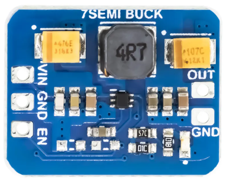
A buck converter is a type of DC-DC converter that steps down voltage while stepping up current. It efficiently converts a higher input voltage to a lower output voltage using a combination of a switching element (typically a transistor), an inductor, a diode, and a capacitor. Buck converters are widely used in power supply systems due to their high efficiency and compact design.
Explore Projects Built with buck
 Open Project in Cirkit Designer
 Open Project in Cirkit Designer
 Open Project in Cirkit Designer
 Open Project in Cirkit Designer
Explore Projects Built with buck
Open Project in Cirkit DesignerOpen Project in Cirkit DesignerOpen Project in Cirkit DesignerOpen Project in Cirkit DesignerCommon Applications and Use Cases
- Powering low-voltage devices from higher-voltage sources (e.g., 12V to 5V conversion)
- Battery-powered systems to regulate voltage
- Embedded systems and microcontrollers
- LED drivers
- Automotive electronics
- Renewable energy systems (e.g., solar charge controllers)
Technical Specifications
Below are the general technical specifications for a typical buck converter. Note that actual values may vary depending on the specific model or design.
Key Technical Details
- Input Voltage Range: 6V to 40V (varies by model)
- Output Voltage Range: 1.2V to 36V (adjustable in most designs)
- Output Current: Up to 10A (depending on the design and cooling)
- Efficiency: Up to 95% (depending on load and input/output conditions)
- Switching Frequency: 100 kHz to 1 MHz
- Operating Temperature: -40°C to 85°C (varies by model)
Pin Configuration and Descriptions
The pinout of a buck converter module (e.g., LM2596-based module) is as follows:
| Pin Name | Description |
|---|---|
| VIN | Input voltage pin. Connect the higher input voltage (e.g., 12V). |
| GND | Ground pin. Connect to the ground of the input and output circuits. |
| VOUT | Output voltage pin. Provides the stepped-down voltage (e.g., 5V). |
| ADJ (optional) | Adjustment pin. Used to set the output voltage (in adjustable models). |
Usage Instructions
How to Use the Component in a Circuit
- Connect the Input Voltage:
- Connect the positive terminal of the input voltage source to the
VINpin. - Connect the negative terminal of the input voltage source to the
GNDpin.
- Connect the positive terminal of the input voltage source to the
- Connect the Load:
- Connect the positive terminal of the load to the
VOUTpin. - Connect the negative terminal of the load to the
GNDpin.
- Connect the positive terminal of the load to the
- Adjust the Output Voltage (if applicable):
- For adjustable buck converters, use the onboard potentiometer or external resistor divider to set the desired output voltage.
- Power On:
- Turn on the input voltage source and measure the output voltage to ensure it matches the desired value before connecting the load.
Important Considerations and Best Practices
- Input Voltage: Ensure the input voltage is within the specified range of the buck converter.
- Output Voltage: Verify the output voltage is correctly set before connecting sensitive devices.
- Heat Dissipation: For high-current applications, ensure proper heat dissipation using heatsinks or active cooling.
- Inductor Selection: Use an inductor with the appropriate current rating to avoid saturation.
- Capacitor Selection: Use low-ESR capacitors to minimize voltage ripple.
- Switching Noise: Place the buck converter module away from sensitive analog circuits to reduce interference.
Example: Using a Buck Converter with Arduino UNO
Below is an example of using a buck converter to power an Arduino UNO from a 12V source:
- Connect the 12V input to the
VINandGNDpins of the buck converter. - Adjust the output voltage to 5V using the onboard potentiometer.
- Connect the
VOUTpin of the buck converter to the5Vpin of the Arduino UNO. - Connect the
GNDpin of the buck converter to theGNDpin of the Arduino UNO.
// Example Arduino code to blink an LED powered by a buck converter
// Ensure the buck converter is set to 5V output before connecting to Arduino

const int ledPin = 13; // Pin connected to the onboard LED

void setup() {
  pinMode(ledPin, OUTPUT); // Set the LED pin as an output
}

void loop() {
  digitalWrite(ledPin, HIGH); // Turn the LED on
  delay(1000);               // Wait for 1 second
  digitalWrite(ledPin, LOW);  // Turn the LED off
  delay(1000);               // Wait for 1 second
}
Troubleshooting and FAQs
Common Issues and Solutions
No Output Voltage:
- Check the input voltage and ensure it is within the specified range.
- Verify all connections are secure and correct.
- Inspect the module for damage (e.g., burnt components).
Output Voltage Too High or Too Low:
- For adjustable models, recheck the potentiometer setting or resistor divider.
- Ensure the load is not drawing more current than the module's rated capacity.
Excessive Heat:
- Ensure the module is not overloaded.
- Add a heatsink or active cooling if necessary.
High Voltage Ripple:
- Use low-ESR capacitors at the input and output.
- Ensure proper grounding and minimize wire lengths.
FAQs
Q: Can I use a buck converter to power a Raspberry Pi?
A: Yes, but ensure the buck converter can provide a stable 5V output with sufficient current (at least 2.5A for most Raspberry Pi models).
Q: What happens if the input voltage drops below the output voltage?
A: The buck converter will stop regulating, and the output voltage will drop below the desired level.
Q: Can I use a buck converter for AC input?
A: No, buck converters are designed for DC input only. Use a rectifier and filter circuit to convert AC to DC before using a buck converter.
Q: How do I calculate the inductor value for a custom buck converter design?
A: The inductor value depends on the input voltage, output voltage, switching frequency, and desired ripple current. Use the formula:
( L = \frac{(V_{in} - V_{out}) \cdot V_{out}}{f_{sw} \cdot I_{ripple} \cdot V_{in}} )
where ( f_{sw} ) is the switching frequency and ( I_{ripple} ) is the peak-to-peak ripple current.
By following this documentation, you can effectively use a buck converter in your projects and troubleshoot common issues.