How to Use Adafruit GPIO Expander Bonnet: Examples, Pinouts, and Specs
Introduction
The Adafruit GPIO Expander Bonnet is a versatile and powerful add-on board designed for the Raspberry Pi. This board utilizes the MCP23017 I2C GPIO expander IC to provide an additional 16 GPIO pins, effectively expanding the capabilities of the Raspberry Pi for projects that require more inputs and outputs. It is particularly useful for interfacing with sensors, LEDs, motors, and other electronic components in complex projects.
Explore Projects Built with Adafruit GPIO Expander Bonnet

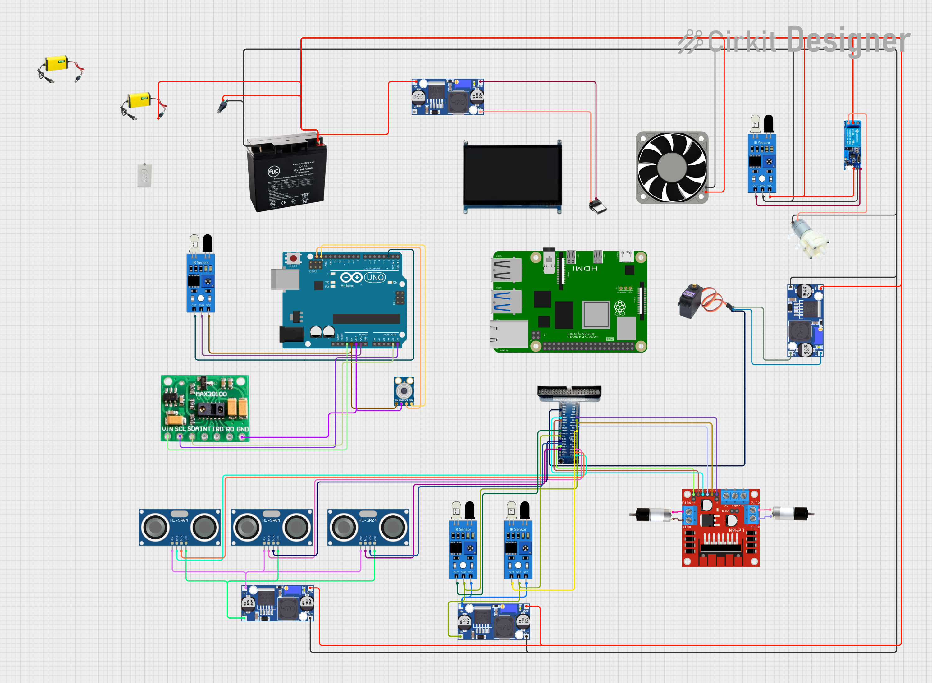

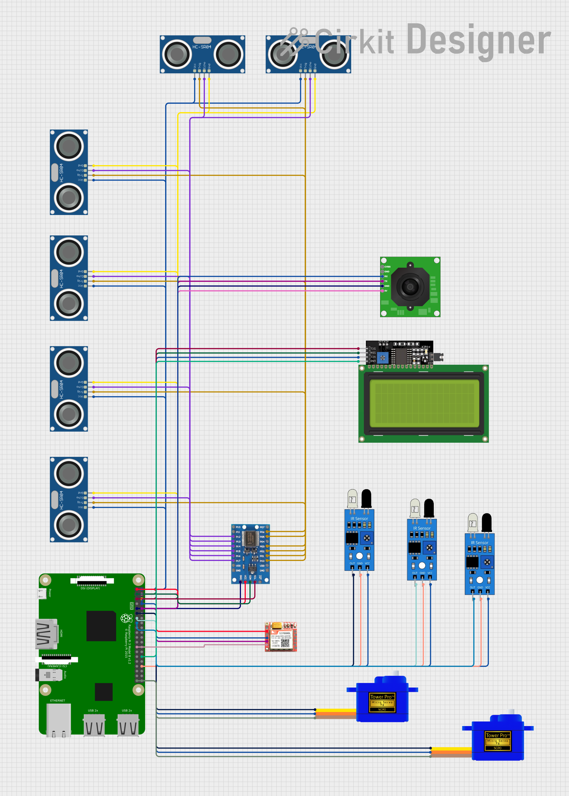
Explore Projects Built with Adafruit GPIO Expander Bonnet
Common Applications and Use Cases
- Home automation systems
- Robotics and control systems
- DIY gaming consoles
- Interactive art installations
- Educational projects and learning platforms
Technical Specifications
Key Technical Details
- Voltage: 3.3V (compatible with Raspberry Pi logic levels)
- Current: 25 mA per pin with a maximum of 150 mA total for all pins
- Communication: I2C interface
- Addressing: Configurable I2C address (default 0x20)
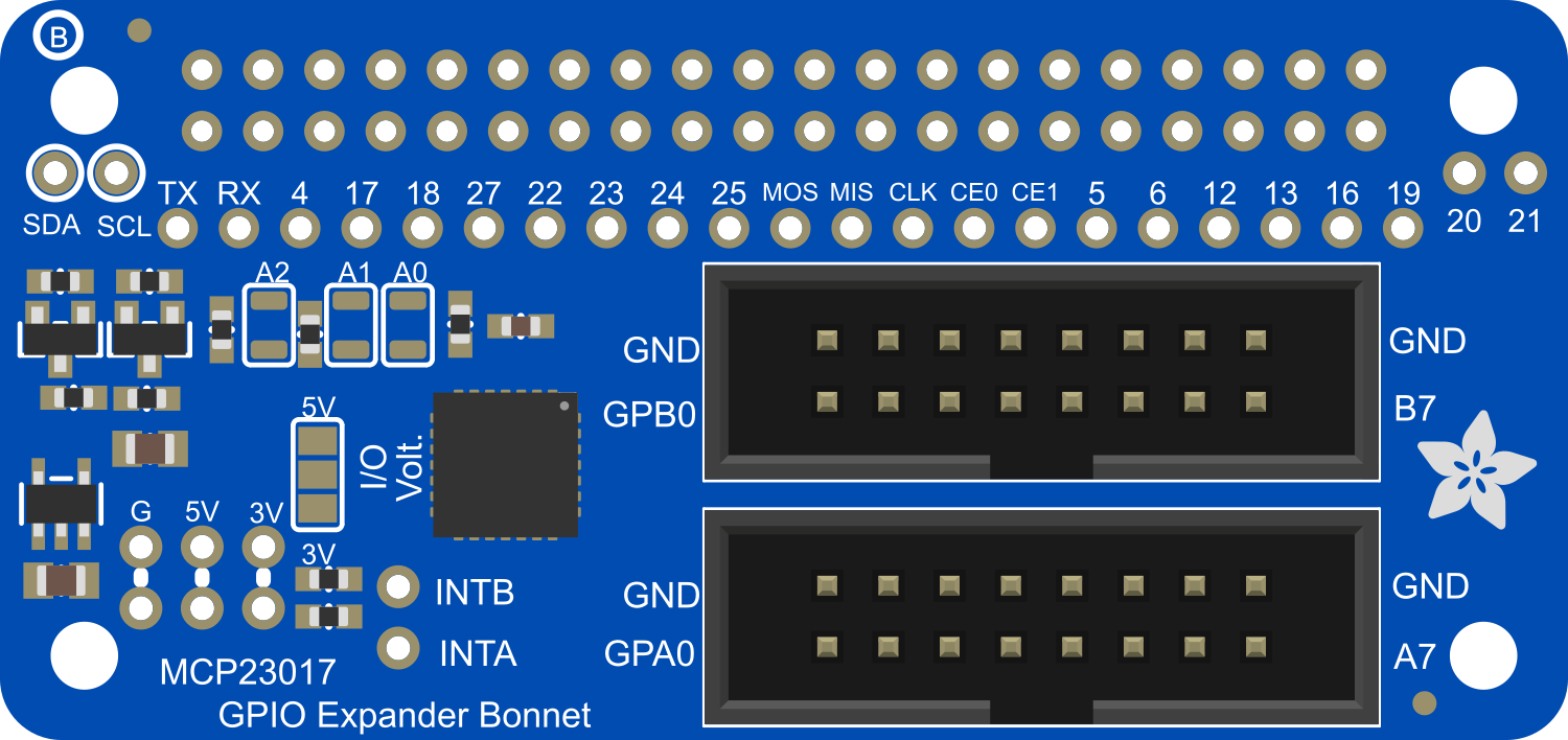
Pin Configuration and Descriptions
| Pin Number | Description | Notes |
|---|---|---|
| 1-16 | GPIO (0-15) | Bidirectional I/O pins |
| A0 | Address Select Pin 0 | Used for I2C address selection |
| A1 | Address Select Pin 1 | Used for I2C address selection |
| A2 | Address Select Pin 2 | Used for I2C address selection |
| VDD | Power Supply | Connect to 3.3V |
| VSS | Ground | Connect to GND |
| SCL | I2C Clock | Connect to SCL on Raspberry Pi |
| SDA | I2C Data | Connect to SDA on Raspberry Pi |
| RESET | Reset Pin | Active-low; typically left open |
Usage Instructions
How to Use the Component in a Circuit
- Mounting: Attach the Adafruit GPIO Expander Bonnet directly onto the GPIO header of the Raspberry Pi.
- Power Connection: Ensure that the VDD pin of the MCP23017 is connected to the 3.3V supply from the Raspberry Pi, and the VSS pin is connected to ground.
- I2C Connection: Connect the SCL and SDA pins of the MCP23017 to the corresponding SCL and SDA pins on the Raspberry Pi.
- Address Selection: Set the A0, A1, and A2 pins to the desired logic levels to configure the I2C address if multiple devices are on the same I2C bus.
- Software Configuration: Enable I2C on the Raspberry Pi and install necessary libraries to communicate with the MCP23017.
Important Considerations and Best Practices
- Ensure that the Raspberry Pi is powered off when attaching or detaching the bonnet to prevent any electrical damage.
- Avoid exceeding the current limit of 25 mA per pin and 150 mA for the entire chip to prevent overheating and damage.
- Use pull-up resistors on the I2C lines if necessary, depending on the length of the connections and the number of I2C devices in the network.
- Always handle the board with care to avoid electrostatic discharge (ESD) damage to the components.
Troubleshooting and FAQs
Common Issues Users Might Face
- I2C Communication Failure: Ensure that the I2C interface is enabled in the Raspberry Pi's configuration and that the correct I2C address is being used in the software.
- Insufficient Power Supply: Verify that the power supply to the Raspberry Pi is stable and capable of delivering sufficient current for the attached peripherals.
- GPIO Pin Not Responding: Check for proper software configuration and initialization of the GPIO pins in the code.
Solutions and Tips for Troubleshooting
- Use the
i2cdetectcommand to verify that the Raspberry Pi can detect the MCP23017 on the I2C bus. - Review the wiring and soldering connections if you encounter intermittent issues or if the device is not recognized.
- Consult the MCP23017 datasheet for detailed information on the operation and configuration of the GPIO expander.
FAQs
Q: Can I stack multiple GPIO Expander Bonnets on a Raspberry Pi? A: Yes, you can stack multiple bonnets by configuring each MCP23017 with a unique I2C address using the A0, A1, and A2 pins.
Q: How do I control the GPIO pins on the Expander Bonnet?
A: You can control the GPIO pins by using I2C commands from the Raspberry Pi to interact with the MCP23017 chip. Libraries such as Adafruit_GPIO can simplify this process.
Q: Is the GPIO Expander Bonnet compatible with all models of Raspberry Pi? A: The bonnet is compatible with any Raspberry Pi model that has a 40-pin GPIO header and supports I2C communication.
Q: What is the maximum voltage and current that can be applied to the GPIO pins? A: The maximum voltage is 3.3V, and the maximum current per pin is 25 mA, with a total chip current of 150 mA.
For further assistance, visit the Adafruit support forums or the Raspberry Pi community forums.
Please note that this documentation is a general guide and may not cover all aspects of the Adafruit GPIO Expander Bonnet. Always refer to the official Adafruit documentation and resources for the most accurate and detailed information.