
How to Use microSD Socket: Examples, Pinouts, and Specs
 Design with microSD Socket in Cirkit Designer
Introduction
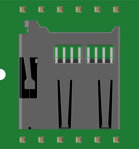
A microSD socket is a small connector designed to interface with microSD cards, enabling data storage and retrieval in electronic devices. It is widely used in applications requiring compact, removable storage solutions. Common use cases include data logging, multimedia storage, firmware updates, and portable devices such as cameras, smartphones, and embedded systems.
Explore Projects Built with microSD Socket
 Open Project in Cirkit Designer
 Open Project in Cirkit Designer
 Open Project in Cirkit Designer
 Open Project in Cirkit Designer
Explore Projects Built with microSD Socket
Open Project in Cirkit DesignerOpen Project in Cirkit DesignerOpen Project in Cirkit DesignerOpen Project in Cirkit DesignerTechnical Specifications
- Type: Push-push or push-pull microSD socket
- Supported Cards: microSD, microSDHC, microSDXC
- Voltage Range: 2.7V to 3.6V (typical operating voltage: 3.3V)
- Current Rating: 500mA (maximum)
- Operating Temperature: -25°C to +85°C
- Durability: 10,000 insertion/removal cycles (typical)
- Mounting Type: Surface Mount Technology (SMT) or Through-Hole Technology (THT)
Pin Configuration and Descriptions
The microSD socket typically has 8 pins. Below is the pinout and description:
| Pin Number | Pin Name | Description |
|---|---|---|
| 1 | DAT2 | Data Line 2 (used in 4-bit mode) |
| 2 | CD/DAT3 | Card Detect/Data Line 3 |
| 3 | CMD | Command/Response Line |
| 4 | VDD | Power Supply (2.7V to 3.6V) |
| 5 | CLK | Clock Signal |
| 6 | VSS | Ground |
| 7 | DAT0 | Data Line 0 |
| 8 | DAT1 | Data Line 1 (used in 4-bit mode) |
Note: Some microSD sockets include an additional pin for card detection (CD) or write protection (WP), depending on the design.
Usage Instructions
How to Use the microSD Socket in a Circuit
- Power Supply: Ensure the microSD socket is powered with a stable 3.3V supply. Use a voltage regulator if your system operates at a higher voltage.
- Connections:
- Connect the
VDDpin to the 3.3V power supply. - Connect the
VSSpin to the ground. - Use pull-up resistors (typically 10kΩ) on the
CMD,CLK, andDATlines for proper signal integrity.
- Connect the
- Microcontroller Interface:
- Use SPI (Serial Peripheral Interface) mode for communication with most microcontrollers.
- Connect the
CMDpin to the SPI MOSI (Master Out Slave In) pin. - Connect the
CLKpin to the SPI clock pin. - Connect the
DAT0pin to the SPI MISO (Master In Slave Out) pin.
- Card Detection: If the socket has a card detect pin (CD), connect it to a GPIO pin on the microcontroller to detect card insertion/removal.
Example: Using a microSD Socket with Arduino UNO
Below is an example of interfacing a microSD socket with an Arduino UNO using the SPI interface:
Circuit Connections
| microSD Socket Pin | Arduino UNO Pin |
|---|---|
| VDD | 3.3V |
| VSS | GND |
| CMD | Pin 11 (MOSI) |
| CLK | Pin 13 (SCK) |
| DAT0 | Pin 12 (MISO) |
| CD (optional) | Pin 10 (CS) |
Arduino Code Example
#include <SPI.h>
#include <SD.h>

// Define the chip select pin for the microSD socket
const int chipSelect = 10;

void setup() {
  // Initialize serial communication for debugging
  Serial.begin(9600);
  while (!Serial) {
    ; // Wait for the serial port to connect (for native USB boards)
  }

  // Initialize the SD card
  Serial.println("Initializing SD card...");
  if (!SD.begin(chipSelect)) {
    Serial.println("Card initialization failed!");
    return;
  }
  Serial.println("Card initialized successfully.");

  // Create a test file on the SD card
  File dataFile = SD.open("test.txt", FILE_WRITE);
  if (dataFile) {
    dataFile.println("Hello, microSD!");
    dataFile.close();
    Serial.println("Data written to test.txt");
  } else {
    Serial.println("Error opening test.txt");
  }
}

void loop() {
  // Nothing to do here
}
Important Considerations and Best Practices
- Voltage Levels: Ensure all signal lines operate at 3.3V logic levels. Use level shifters if your microcontroller operates at 5V.
- ESD Protection: Add ESD protection diodes to prevent damage from electrostatic discharge.
- Decoupling Capacitors: Place a 0.1µF ceramic capacitor close to the
VDDpin for power supply stability. - Signal Integrity: Keep the SPI lines as short as possible to reduce noise and improve signal quality.
- File System: Format the microSD card with the FAT16 or FAT32 file system for compatibility with most libraries.
Troubleshooting and FAQs
Common Issues
Card Initialization Fails:
- Cause: Incorrect wiring or insufficient power supply.
- Solution: Double-check all connections and ensure the power supply is stable at 3.3V.
Data Corruption:
- Cause: Improper handling of the card during read/write operations.
- Solution: Always close files after writing and avoid removing the card while in use.
Card Not Detected:
- Cause: Faulty card detect pin or damaged socket.
- Solution: Test the card detect pin with a multimeter or replace the socket if necessary.
Slow Data Transfer:
- Cause: Using a low-speed microSD card or improper SPI clock settings.
- Solution: Use a high-speed microSD card (Class 10 or higher) and optimize SPI clock speed.
FAQs
Q: Can I use a 5V microcontroller with a microSD socket?
A: Yes, but you must use level shifters to convert 5V signals to 3.3V.Q: What is the maximum storage capacity supported?
A: This depends on the microcontroller library. Most libraries support up to 32GB (microSDHC). For larger capacities, ensure the library supports microSDXC.Q: How do I safely remove the microSD card?
A: Ensure all files are closed and no read/write operations are in progress before removing the card.Q: Can I use the microSD socket for non-SPI communication?
A: Yes, the microSD socket supports both SPI and SDIO modes, but SDIO requires additional hardware and software support.
By following this documentation, you can effectively integrate and troubleshoot a microSD socket in your electronic projects.