How to Use push button: Examples, Pinouts, and Specs
Introduction
A push button is a momentary switch that completes a circuit when pressed and breaks the circuit when released. It is one of the simplest and most commonly used input devices in electronics. Push buttons are widely used in applications such as user interfaces, control panels, and embedded systems. They are ideal for triggering events, toggling states, or providing user input in a variety of electronic devices.
Explore Projects Built with push button


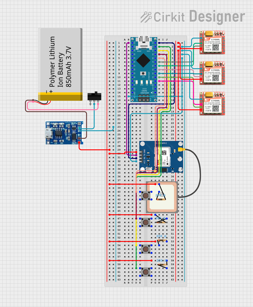
Explore Projects Built with push button
Technical Specifications
- Type: Momentary switch
- Contact Configuration: Normally Open (NO) or Normally Closed (NC)
- Operating Voltage: Typically 3.3V to 12V (depends on the circuit design)
- Current Rating: 50mA to 500mA (varies by model)
- Debounce Time: ~5ms to 20ms (mechanical property)
- Lifespan: 100,000 to 1,000,000 actuations (varies by model)
- Mounting Type: Through-hole or surface-mount
Pin Configuration and Descriptions
Push buttons typically have two or four pins. The table below describes the pin configuration for a standard 4-pin push button:
| Pin Number | Description |
|---|---|
| 1 | Terminal 1 for the switch connection |
| 2 | Terminal 2 for the switch connection |
| 3 | Internally connected to Pin 1 |
| 4 | Internally connected to Pin 2 |
Note: Pins 1 and 3 are internally connected, as are Pins 2 and 4. This allows the button to be used in either orientation.
Usage Instructions
How to Use the Push Button in a Circuit
Basic Connection:
- Connect one terminal of the push button to the input pin of a microcontroller or circuit.
- Connect the other terminal to ground (GND).
- Use a pull-up resistor (typically 10kΩ) between the input pin and the positive voltage supply (Vcc) to ensure a stable HIGH signal when the button is not pressed.
Debouncing:
- Mechanical push buttons can produce noise or "bouncing" when pressed or released. Use a software debounce routine or a hardware debounce circuit (e.g., an RC filter) to ensure stable operation.
Example Circuit:
- Connect the push button to an Arduino UNO as follows:
- One terminal to digital pin 2.
- The other terminal to GND.
- Add a 10kΩ pull-up resistor between digital pin 2 and 5V.
- Connect the push button to an Arduino UNO as follows:
Arduino UNO Example Code
// Push Button Example Code for Arduino UNO
// This code reads the state of a push button and turns on an LED when pressed.

const int buttonPin = 2;  // Pin connected to the push button
const int ledPin = 13;    // Pin connected to the onboard LED

void setup() {
  pinMode(buttonPin, INPUT_PULLUP); // Set button pin as input with internal pull-up
  pinMode(ledPin, OUTPUT);          // Set LED pin as output
}

void loop() {
  int buttonState = digitalRead(buttonPin); // Read the button state

  if (buttonState == LOW) { // Button pressed (LOW due to pull-up resistor)
    digitalWrite(ledPin, HIGH); // Turn on the LED
  } else {
    digitalWrite(ledPin, LOW);  // Turn off the LED
  }
}
Important Considerations and Best Practices
- Always use a pull-up or pull-down resistor to avoid floating input states.
- For high-speed circuits, consider using a hardware debounce circuit to eliminate noise.
- Ensure the push button's current and voltage ratings match your circuit requirements.
- Avoid excessive force when pressing the button to prolong its lifespan.
Troubleshooting and FAQs
Common Issues and Solutions
Button Not Responding:
- Cause: No pull-up or pull-down resistor.
- Solution: Add a 10kΩ pull-up or pull-down resistor to stabilize the input signal.
Button Produces Erratic Behavior:
- Cause: Mechanical bouncing.
- Solution: Implement a debounce routine in software or use an RC filter.
Button Works Intermittently:
- Cause: Loose or poor connections.
- Solution: Check and secure all connections. Ensure solder joints are solid.
Button Feels Stuck or Hard to Press:
- Cause: Physical damage or debris.
- Solution: Clean the button or replace it if damaged.
FAQs
Q: Can I use a push button without a microcontroller?
- A: Yes, push buttons can be used in simple circuits to control LEDs, relays, or other components directly.
Q: What is the difference between Normally Open (NO) and Normally Closed (NC) buttons?
- A: An NO button completes the circuit when pressed, while an NC button breaks the circuit when pressed.
Q: How do I debounce a push button in software?
- A: Use a delay (e.g., 10ms) after detecting a button press to ignore bouncing signals.
Q: Can I use a push button with a 3.3V system?
- A: Yes, as long as the button's voltage and current ratings are compatible with the system.
By following this documentation, you can effectively integrate a push button into your electronic projects!