Cirkit Designer Logo
Cirkit Designer
Your all-in-one circuit design IDE
Home / 
Component Documentation

How to Use RFID (ID12): Examples, Pinouts, and Specs

Image of RFID (ID12)
Cirkit Designer LogoDesign with RFID (ID12) in Cirkit Designer

Introduction

The ID12 is a compact RFID (Radio-Frequency Identification) module that provides a simple and efficient way to integrate RFID technology into various electronic projects. RFID technology uses electromagnetic fields to automatically identify and track tags attached to objects. The ID12 module is particularly useful in applications such as access control systems, asset tracking, and identification.

Explore Projects Built with RFID (ID12)

Use Cirkit Designer to design, explore, and prototype these projects online. Some projects support real-time simulation. Click "Open Project" to start designing instantly!
Biometric Access Control System with RFID and Touch Activation
Image of DOORLOCK1: A project utilizing RFID (ID12) in a practical application
This circuit is designed for security and identification purposes, featuring an RFID-RC522 module for contactless communication and a fingerprint scanner for biometric authentication. It includes an LCD display for user interaction, a touch sensor for input, a buzzer for audio feedback, and a relay module for controlling external devices. The components are interfaced with a NANO Expansion board, which likely contains a microcontroller to coordinate the operations of the system.
Cirkit Designer LogoOpen Project in Cirkit Designer
Arduino UNO RFID Reader Interface Project
Image of INTERNAL DESIGN MAIN STUDY: A project utilizing RFID (ID12) in a practical application
This is an RFID tag reading system. An Arduino UNO is interfaced with an RFID-RC522 module using digital pins D5, D10, D11, and D13 through resistors, with direct MISO connection to D12. The system is designed to read RFID tags and handle the data with the Arduino.
Cirkit Designer LogoOpen Project in Cirkit Designer
Arduino and ESP8266 RFID Door Lock System with WiFi Connectivity
Image of SmartDoorLock: A project utilizing RFID (ID12) in a practical application
This circuit features an Arduino UNO connected to an RFID-RC522 module for RFID scanning and an ESP8266 ESP-12E WiFi module for wireless communication. The Arduino controls a KY-019 Relay module, which in turn drives a 12V solenoid lock, allowing the lock to be actuated based on RFID card detection or potentially remote commands via WiFi. The Arduino's embedded code is set up to initialize the RFID reader and output the UID of scanned cards to the serial monitor.
Cirkit Designer LogoOpen Project in Cirkit Designer
Arduino-Based RFID Controlled Solenoid Lock with LED Indicators
Image of projeto1: A project utilizing RFID (ID12) in a practical application
This circuit is an RFID-based access control system. The Arduino 101 reads RFID tags using the RFID-RC522 module and controls a relay to unlock a 12V solenoid lock. LEDs provide visual feedback for the system's status.
Cirkit Designer LogoOpen Project in Cirkit Designer

Explore Projects Built with RFID (ID12)

Use Cirkit Designer to design, explore, and prototype these projects online. Some projects support real-time simulation. Click "Open Project" to start designing instantly!
Image of DOORLOCK1: A project utilizing RFID (ID12) in a practical application
Biometric Access Control System with RFID and Touch Activation
This circuit is designed for security and identification purposes, featuring an RFID-RC522 module for contactless communication and a fingerprint scanner for biometric authentication. It includes an LCD display for user interaction, a touch sensor for input, a buzzer for audio feedback, and a relay module for controlling external devices. The components are interfaced with a NANO Expansion board, which likely contains a microcontroller to coordinate the operations of the system.
Cirkit Designer LogoOpen Project in Cirkit Designer
Image of INTERNAL DESIGN MAIN STUDY: A project utilizing RFID (ID12) in a practical application
Arduino UNO RFID Reader Interface Project
This is an RFID tag reading system. An Arduino UNO is interfaced with an RFID-RC522 module using digital pins D5, D10, D11, and D13 through resistors, with direct MISO connection to D12. The system is designed to read RFID tags and handle the data with the Arduino.
Cirkit Designer LogoOpen Project in Cirkit Designer
Image of SmartDoorLock: A project utilizing RFID (ID12) in a practical application
Arduino and ESP8266 RFID Door Lock System with WiFi Connectivity
This circuit features an Arduino UNO connected to an RFID-RC522 module for RFID scanning and an ESP8266 ESP-12E WiFi module for wireless communication. The Arduino controls a KY-019 Relay module, which in turn drives a 12V solenoid lock, allowing the lock to be actuated based on RFID card detection or potentially remote commands via WiFi. The Arduino's embedded code is set up to initialize the RFID reader and output the UID of scanned cards to the serial monitor.
Cirkit Designer LogoOpen Project in Cirkit Designer
Image of projeto1: A project utilizing RFID (ID12) in a practical application
Arduino-Based RFID Controlled Solenoid Lock with LED Indicators
This circuit is an RFID-based access control system. The Arduino 101 reads RFID tags using the RFID-RC522 module and controls a relay to unlock a 12V solenoid lock. LEDs provide visual feedback for the system's status.
Cirkit Designer LogoOpen Project in Cirkit Designer

Common Applications and Use Cases

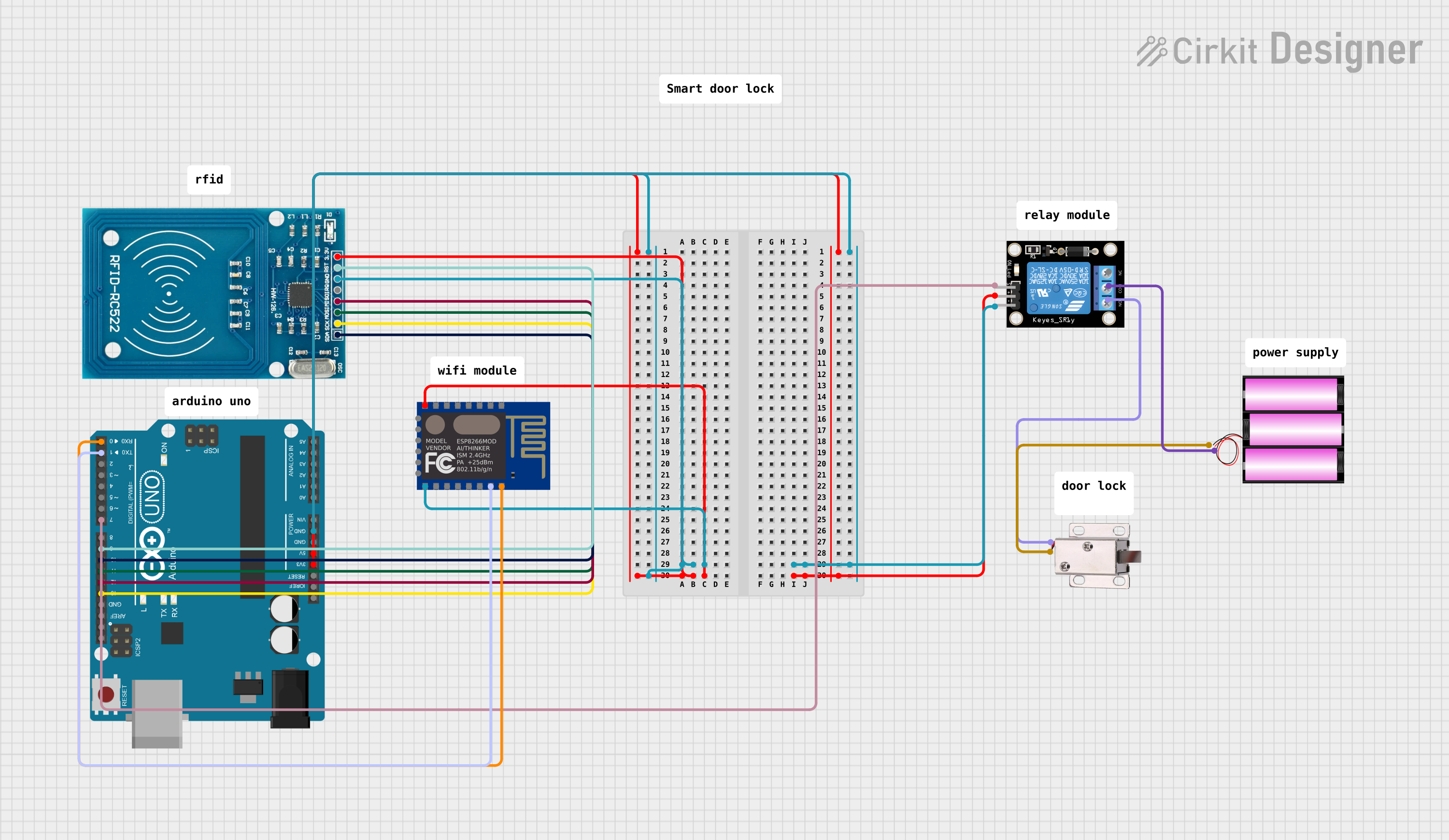
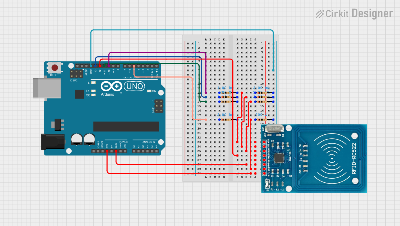
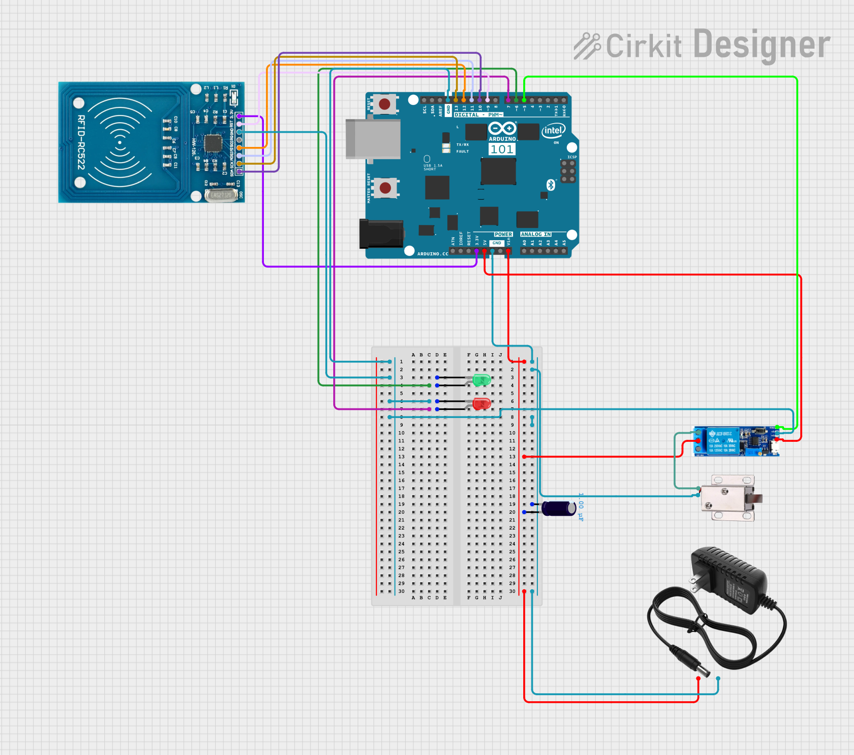
  • Access Control: The ID12 can be used to read RFID tags for secure entry systems.
  • Asset Tracking: Track equipment or inventory by tagging and scanning items.
  • Identification: Quickly identify tagged items or individuals for various purposes.

Technical Specifications

Key Technical Details

  • Operating Frequency: 125 kHz
  • Interface: Serial TTL
  • Voltage Requirements: 2.8V to 5V DC
  • Current Requirements: 50mA (typical)
  • Read Range: Up to 120mm with a 125kHz passive tag
  • Antenna: Built-in

Pin Configuration and Descriptions

Pin Number Name Description
1 VCC Power supply (2.8V to 5V DC)
2 /RES Reset pin (active low)
3 GND Ground connection
4 TX Serial data output (TTL level)
5 AN Analog output (not used in digital mode)
6 D0 Format selector (ground for ASCII, VCC for Wiegand)
7 D1 Format selector (ground for ASCII, VCC for Wiegand)
8 /FMT Format selector (ground for 9600bps, VCC for 19200bps)
9 SHD Shield ground (connected to the module's shield)
10 N/C Not connected

Usage Instructions

How to Use the Component in a Circuit

  1. Power Supply: Connect the VCC pin to a 2.8V to 5V power source and the GND pin to the ground.
  2. Serial Communication: Connect the TX pin to the RX pin of your microcontroller to receive the data from the RFID module.
  3. Reset (Optional): The /RES pin can be connected to a digital pin on your microcontroller if you wish to reset the module programmatically.
  4. Format Selection: Use the D0, D1, and /FMT pins to select the output format and baud rate according to your requirements.

Important Considerations and Best Practices

  • Ensure that the power supply is within the specified voltage range to prevent damage.
  • Place the RFID module away from metal surfaces to avoid interference with the antenna.
  • When designing the enclosure, provide a clear path between the RFID tag and the module's antenna for optimal read range.
  • Use proper decoupling capacitors close to the module's power pins to filter out noise.

Troubleshooting and FAQs

Common Issues

  • Read Range Issues: Ensure there are no metal objects near the antenna and that the RFID tags are compatible with the module's frequency.
  • Communication Errors: Verify the baud rate and format settings. Check the serial connection to the microcontroller.

Solutions and Tips for Troubleshooting

  • If the module is not responding, try resetting it using the /RES pin.
  • Double-check the wiring, especially the power supply and ground connections.
  • Ensure that the RFID tags are within the specified read range and properly oriented.

FAQs

Q: Can the ID12 read multiple tags at once? A: No, the ID12 is designed to read one tag at a time.

Q: What should I do if the module is not reading tags? A: Check the power supply, ensure the antenna is not obstructed, and verify that the tags are compatible and not damaged.

Q: How can I extend the read range of the ID12? A: The read range is largely determined by the module's design and the tag's antenna. Using tags with larger antennas can improve the read range.

Example Code for Arduino UNO

#include <SoftwareSerial.h>

SoftwareSerial RFID(10, 11); // RX and TX
int data = 0;

void setup() {
  RFID.begin(9600); // Start serial to RFID reader
  Serial.begin(9600); // Start serial to PC
}

void loop() {
  if (RFID.available() > 0) {
    // Check for data from RFID reader
    data = RFID.read(); // Read the data
    Serial.print(char(data)); // Print the data to the Serial monitor
  }
}

Note: This example assumes that the ID12 module is set to ASCII output mode at 9600bps. Adjust the pin numbers and settings as needed for your specific setup.