How to Use Analog Sound Sensor: Examples, Pinouts, and Specs
Introduction
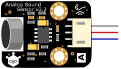
The Analog Sound Sensor is a device designed to detect sound levels and convert them into an analog voltage signal. This allows users to measure sound intensity in real-time. The sensor is commonly used in audio-related projects, sound-activated systems, and environmental monitoring applications. Its simplicity and versatility make it a popular choice for hobbyists and professionals alike.
Explore Projects Built with Analog Sound Sensor
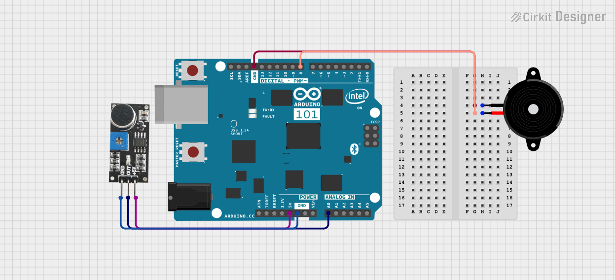
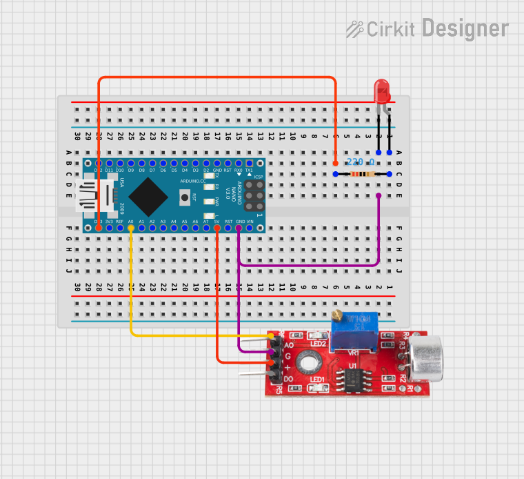
Explore Projects Built with Analog Sound Sensor
Common Applications and Use Cases
- Sound-activated lighting systems
- Voice-activated devices
- Environmental noise monitoring
- Audio visualization projects
- Security systems for detecting loud noises or disturbances
Technical Specifications
The following table outlines the key technical details of the Analog Sound Sensor:
| Parameter | Value |
|---|---|
| Operating Voltage | 3.3V to 5V |
| Output Signal | Analog voltage (0V to Vcc) |
| Sensitivity Range | Adjustable via onboard potentiometer |
| Frequency Response | 50 Hz to 10 kHz |
| Dimensions | Typically 32mm x 17mm x 8mm |
Pin Configuration and Descriptions
The Analog Sound Sensor typically has three pins. The table below describes each pin:
| Pin | Name | Description |
|---|---|---|
| 1 | VCC | Power supply pin (3.3V to 5V) |
| 2 | GND | Ground connection |
| 3 | OUT | Analog output pin that provides a voltage signal |
Usage Instructions
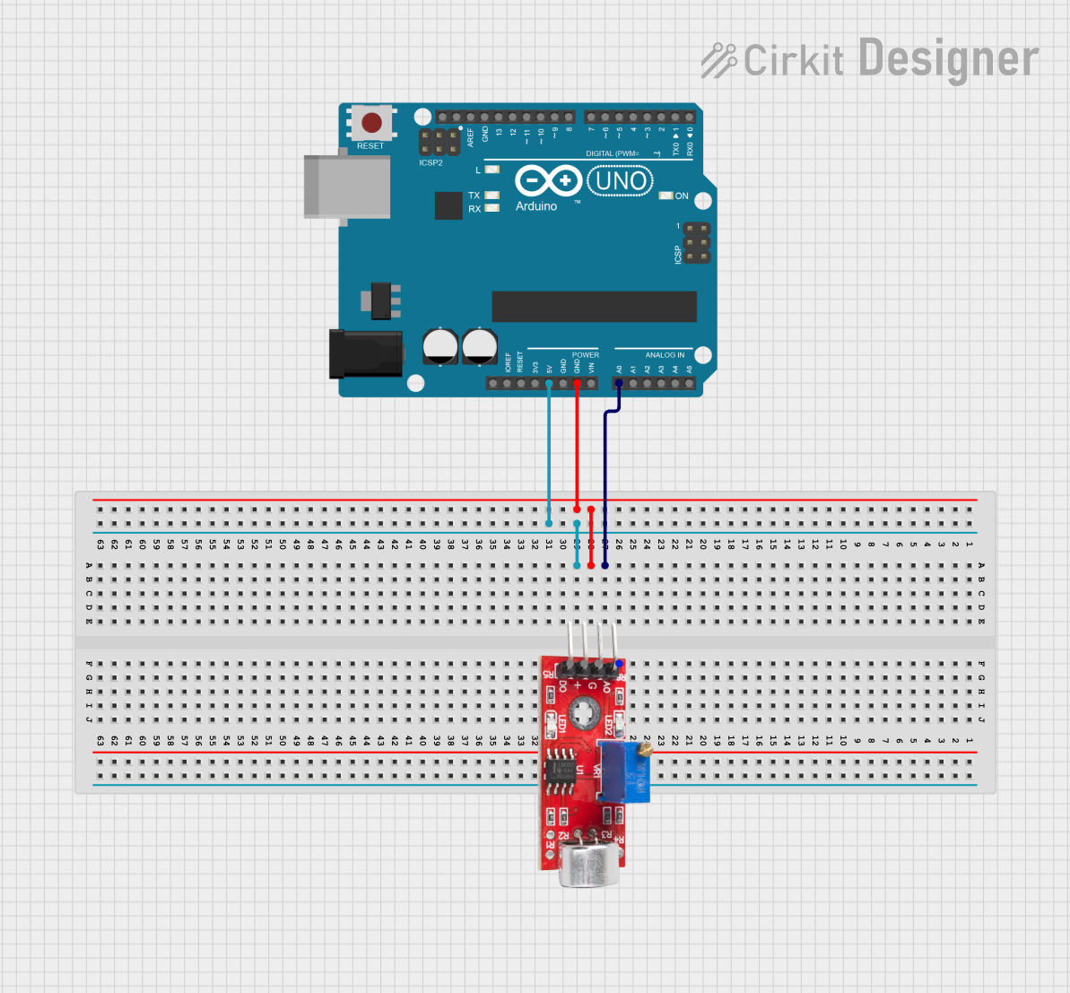
How to Use the Component in a Circuit
- Connect the Power Supply:
- Connect the
VCCpin to a 3.3V or 5V power source. - Connect the
GNDpin to the ground of your circuit.
- Connect the
- Connect the Output:
- Connect the
OUTpin to an analog input pin of your microcontroller (e.g., Arduino).
- Connect the
- Adjust Sensitivity:
- Use the onboard potentiometer to adjust the sensitivity of the sensor. Turning it clockwise increases sensitivity, while turning it counterclockwise decreases it.
Important Considerations and Best Practices
- Power Supply: Ensure the sensor operates within its specified voltage range (3.3V to 5V). Exceeding this range may damage the sensor.
- Noise Filtering: The sensor may pick up ambient noise. Use software filtering techniques to process the signal for more accurate results.
- Placement: Place the sensor away from sources of electrical noise or vibrations to avoid false readings.
- Calibration: Adjust the potentiometer to calibrate the sensor for your specific application.
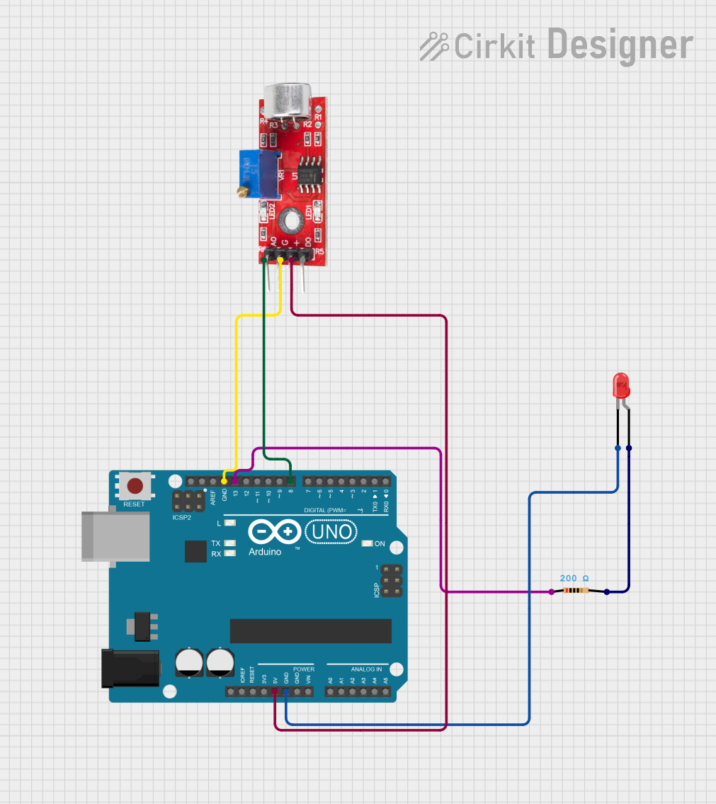
Example: Connecting to an Arduino UNO
Below is an example of how to use the Analog Sound Sensor with an Arduino UNO to read sound levels:
// Define the analog pin connected to the sensor's OUT pin
const int soundSensorPin = A0;

// Variable to store the analog value from the sensor
int soundLevel;

void setup() {
  // Initialize serial communication for debugging
  Serial.begin(9600);
}

void loop() {
  // Read the analog value from the sound sensor
  soundLevel = analogRead(soundSensorPin);

  // Print the sound level to the Serial Monitor
  Serial.print("Sound Level: ");
  Serial.println(soundLevel);

  // Add a small delay to stabilize readings
  delay(100);
}
Note: The soundLevel variable will contain values between 0 and 1023, corresponding to the analog voltage output of the sensor. You can map these values to a specific range if needed.
Troubleshooting and FAQs
Common Issues and Solutions
No Output or Constant Values:
- Cause: Incorrect wiring or insufficient power supply.
- Solution: Double-check the connections and ensure the power supply is within the specified range.
Inconsistent or Noisy Readings:
- Cause: Ambient noise or electrical interference.
- Solution: Place the sensor in a quieter environment or use software filtering to smooth the readings.
Sensor Not Responding to Sound:
- Cause: Sensitivity is too low.
- Solution: Adjust the potentiometer to increase the sensitivity.
Output Stuck at Maximum Value:
- Cause: Sensitivity is too high or the sensor is too close to a loud sound source.
- Solution: Decrease the sensitivity using the potentiometer or move the sensor further from the sound source.
FAQs
Q1: Can the Analog Sound Sensor detect specific frequencies?
A1: No, the sensor is designed to measure overall sound intensity and does not differentiate between specific frequencies.
Q2: Can I use this sensor with a 3.3V microcontroller?
A2: Yes, the sensor operates within a voltage range of 3.3V to 5V, making it compatible with 3.3V microcontrollers like the ESP32.
Q3: How do I process the analog signal for more accurate results?
A3: You can use software techniques such as averaging multiple readings or applying a low-pass filter to reduce noise and improve accuracy.
Q4: Is this sensor suitable for outdoor use?
A4: The sensor is not weatherproof. If you plan to use it outdoors, ensure it is protected from moisture and extreme temperatures.