
Cirkit Designer
Your all-in-one circuit design IDE
Home /
Component Documentation
How to Use ADXL345: Examples, Pinouts, and Specs
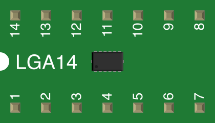
 Design with ADXL345 in Cirkit Designer
Introduction
The ADXL345 is a small, thin, low-power, 3-axis accelerometer capable of high-resolution (13-bit) measurements at up to ±16g. It is designed for applications requiring precise motion sensing, tilt detection, and gesture recognition. The device supports both I2C and SPI communication protocols, making it versatile and easy to integrate into a wide range of systems.
Explore Projects Built with ADXL345
Arduino Nano and ADXL345 Accelerometer Interface
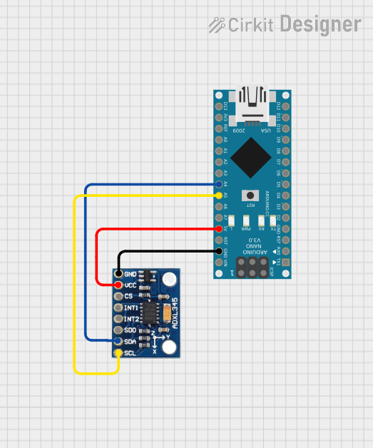
This circuit features an Arduino Nano interfaced with an ADXL345 accelerometer for measuring acceleration. The Arduino provides power and I2C communication to the accelerometer, enabling it to capture and process motion-related data.
Open Project in Cirkit DesignerArduino Leonardo and ADXL345 Accelerometer-Based Motion Detection System
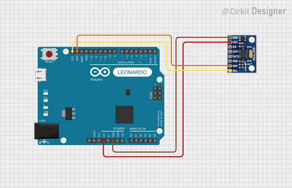
This circuit interfaces an ADXL345 accelerometer with an Arduino Leonardo via I2C communication. The Arduino provides power and ground to the accelerometer and reads acceleration data through the SDA and SCL lines.
Open Project in Cirkit DesignerArduino UNO and ADXL345 Accelerometer Data Logger
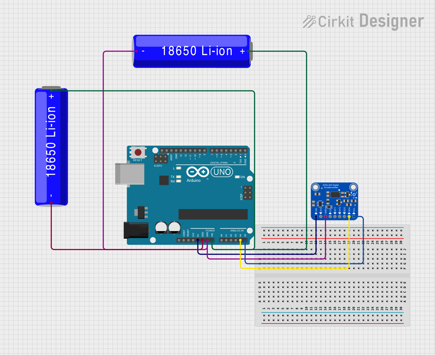
This circuit features an Arduino UNO microcontroller interfaced with an Adafruit ADXL345 accelerometer for motion detection, powered by two parallel-connected 18650 Li-ion batteries. The accelerometer communicates with the Arduino over I2C, and the system is designed for further code development to utilize the motion sensing capabilities.
Open Project in Cirkit DesignerESP32-Based Multi-Sensor Monitoring System with Battery Power
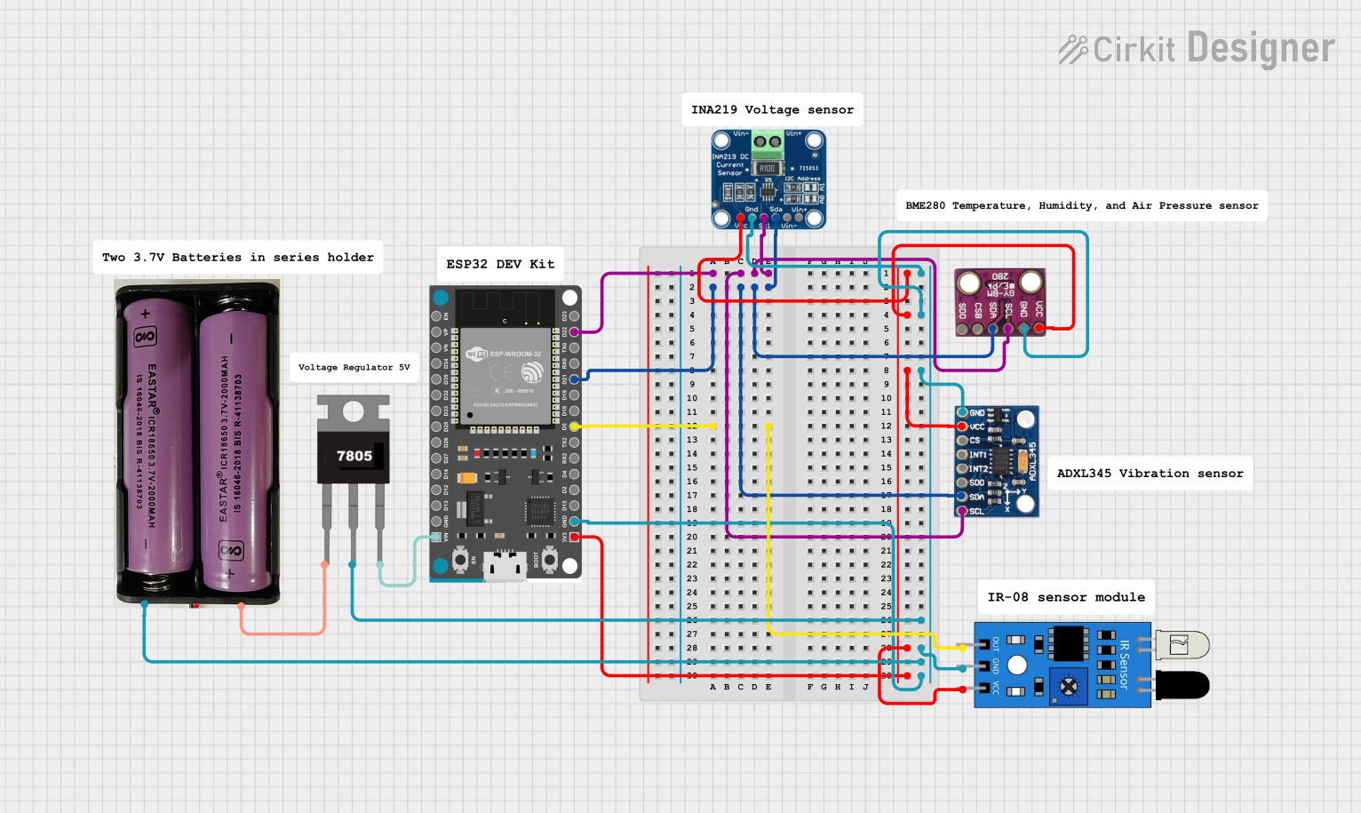
This circuit is a sensor monitoring system powered by a 7.4V battery, regulated to 5V using a 7805 voltage regulator. It uses an ESP32 microcontroller to interface with an ADXL345 accelerometer, INA219 current sensor, BMP280 pressure sensor, and an IR sensor, all connected via I2C and GPIO for data acquisition and processing.
Open Project in Cirkit DesignerExplore Projects Built with ADXL345
Arduino Nano and ADXL345 Accelerometer Interface
This circuit features an Arduino Nano interfaced with an ADXL345 accelerometer for measuring acceleration. The Arduino provides power and I2C communication to the accelerometer, enabling it to capture and process motion-related data.
Open Project in Cirkit DesignerArduino Leonardo and ADXL345 Accelerometer-Based Motion Detection System
This circuit interfaces an ADXL345 accelerometer with an Arduino Leonardo via I2C communication. The Arduino provides power and ground to the accelerometer and reads acceleration data through the SDA and SCL lines.
Open Project in Cirkit DesignerArduino UNO and ADXL345 Accelerometer Data Logger
This circuit features an Arduino UNO microcontroller interfaced with an Adafruit ADXL345 accelerometer for motion detection, powered by two parallel-connected 18650 Li-ion batteries. The accelerometer communicates with the Arduino over I2C, and the system is designed for further code development to utilize the motion sensing capabilities.
Open Project in Cirkit DesignerESP32-Based Multi-Sensor Monitoring System with Battery Power
This circuit is a sensor monitoring system powered by a 7.4V battery, regulated to 5V using a 7805 voltage regulator. It uses an ESP32 microcontroller to interface with an ADXL345 accelerometer, INA219 current sensor, BMP280 pressure sensor, and an IR sensor, all connected via I2C and GPIO for data acquisition and processing.
Open Project in Cirkit DesignerCommon Applications
- Motion sensing in portable devices
- Tilt and orientation detection
- Gesture recognition for user interfaces
- Vibration monitoring in industrial systems
- Gaming and virtual reality controllers
Technical Specifications
Key Technical Details
- Measurement Range: ±2g, ±4g, ±8g, ±16g (selectable)
- Resolution: 13-bit
- Supply Voltage: 2.0V to 3.6V
- Communication Protocols: I2C (up to 400 kHz) and SPI (up to 5 MHz)
- Power Consumption:
- Normal mode: 40 µA
- Standby mode: 0.1 µA
- Operating Temperature: -40°C to +85°C
- Output Data Rate (ODR): 0.1 Hz to 3200 Hz
- Dimensions: 3 mm × 5 mm × 1 mm (LFCSP package)
Pin Configuration and Descriptions
The ADXL345 has 14 pins. Below is the pinout and description:
| Pin | Name | Description |
|---|---|---|
| 1 | VDD | Power supply input (2.0V to 3.6V). |
| 2 | GND | Ground. |
| 3 | CS | Chip Select. Used to select SPI (active low). Tie high for I2C mode. |
| 4 | INT1 | Interrupt 1 output. Configurable for various interrupt events. |
| 5 | INT2 | Interrupt 2 output. Configurable for various interrupt events. |
| 6 | SCL/SCLK | Serial clock line for I2C or SPI. |
| 7 | SDA/SDI/SDO | Data line for I2C or SPI. |
| 8 | NC | No connection. Leave unconnected. |
| 9-14 | NC | No connection. Leave unconnected. |
Usage Instructions
How to Use the ADXL345 in a Circuit
- Power Supply: Connect the VDD pin to a 3.3V power source and the GND pin to ground.
- Communication Protocol:
- For I2C: Tie the CS pin high and connect the SCL and SDA pins to the corresponding I2C lines of your microcontroller. Use pull-up resistors (typically 4.7 kΩ) on the SCL and SDA lines.
- For SPI: Tie the CS pin low and connect the SCL, SDA, and CS pins to the corresponding SPI lines of your microcontroller.
- Interrupts: Connect INT1 and/or INT2 to your microcontroller if you need to use interrupt-driven features.
- Bypass Capacitor: Place a 0.1 µF ceramic capacitor close to the VDD pin for power supply decoupling.
Important Considerations and Best Practices
- Voltage Levels: Ensure the logic levels of your microcontroller match the ADXL345's voltage requirements (2.0V to 3.6V).
- Mounting: Minimize mechanical stress on the ADXL345 to avoid inaccurate readings.
- Data Rate: Choose an appropriate output data rate (ODR) based on your application to balance power consumption and performance.
- Calibration: Perform calibration to account for offsets and scale factors for accurate measurements.
Example Code for Arduino UNO (I2C Mode)
#include <Wire.h> // Include the Wire library for I2C communication

#define ADXL345_ADDRESS 0x53 // I2C address of the ADXL345

void setup() {
  Wire.begin(); // Initialize I2C communication
  Serial.begin(9600); // Start serial communication for debugging

  // Initialize the ADXL345
  Wire.beginTransmission(ADXL345_ADDRESS);
  Wire.write(0x2D); // Power control register
  Wire.write(0x08); // Set the device to measurement mode
  Wire.endTransmission();

  // Set data format to ±2g and full resolution
  Wire.beginTransmission(ADXL345_ADDRESS);
  Wire.write(0x31); // Data format register
  Wire.write(0x08); // Full resolution, ±2g
  Wire.endTransmission();
}

void loop() {
  int16_t x, y, z;

  // Request 6 bytes of data from the ADXL345 (X, Y, Z axes)
  Wire.beginTransmission(ADXL345_ADDRESS);
  Wire.write(0x32); // Start reading from the DATAX0 register
  Wire.endTransmission(false);
  Wire.requestFrom(ADXL345_ADDRESS, 6);

  if (Wire.available() == 6) {
    x = Wire.read() | (Wire.read() << 8); // Combine low and high bytes for X-axis
    y = Wire.read() | (Wire.read() << 8); // Combine low and high bytes for Y-axis
    z = Wire.read() | (Wire.read() << 8); // Combine low and high bytes for Z-axis
  }

  // Print the accelerometer readings
  Serial.print("X: "); Serial.print(x);
  Serial.print(" Y: "); Serial.print(y);
  Serial.print(" Z: "); Serial.println(z);

  delay(500); // Delay for readability
}
Troubleshooting and FAQs
Common Issues
No Communication with the ADXL345:
- Ensure the correct I2C address (0x53) is being used.
- Verify pull-up resistors are present on the I2C lines.
- Check the wiring and ensure the CS pin is tied high for I2C mode.
Incorrect or No Data:
- Confirm the ADXL345 is in measurement mode (check the power control register).
- Verify the data format register is configured correctly for your application.
High Noise in Readings:
- Ensure proper decoupling capacitors are used near the power supply pins.
- Minimize vibrations or mechanical stress on the sensor.
Tips for Troubleshooting
- Use a logic analyzer or oscilloscope to verify I2C or SPI signals.
- Check the power supply voltage to ensure it is within the specified range.
- Test the ADXL345 with a simple example code to confirm basic functionality before integrating it into a larger project.