How to Use LED MATRIX P5: Examples, Pinouts, and Specs
Introduction
The P5 LED matrix is a versatile display module consisting of a grid of light-emitting diodes (LEDs) arranged with a 5mm pitch (distance between adjacent LEDs). This compact design allows for the display of text, images, and animations with high brightness and clarity. The P5 LED matrix is widely used in digital signage, advertising displays, scoreboards, and decorative lighting applications. Its modular design enables users to combine multiple panels to create larger displays.
Explore Projects Built with LED MATRIX P5


Explore Projects Built with LED MATRIX P5
Technical Specifications
Below are the key technical details of the P5 LED matrix:
| Parameter | Specification |
|---|---|
| Pixel Pitch | 5mm |
| Resolution | Typically 32x32 or 64x32 pixels |
| LED Type | SMD (Surface-Mount Device) LEDs |
| Operating Voltage | 5V DC |
| Power Consumption | ~20W per panel (varies by usage) |
| Refresh Rate | ≥1920Hz |
| Brightness | ≥1200 cd/m² |
| Viewing Angle | Horizontal: 120°, Vertical: 120° |
| Dimensions (per panel) | 320mm x 160mm (for 64x32 resolution) |
| Interface | HUB75 |
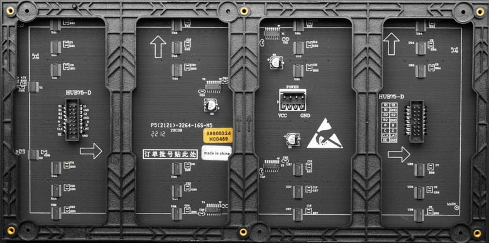
Pin Configuration and Descriptions
The P5 LED matrix typically uses a HUB75 interface for communication. Below is the pin configuration for the HUB75 connector:
| Pin | Name | Description |
|---|---|---|
| 1 | GND | Ground connection |
| 2 | A | Row address signal A |
| 3 | B | Row address signal B |
| 4 | C | Row address signal C |
| 5 | D | Row address signal D (used for larger matrices) |
| 6 | CLK | Clock signal for data synchronization |
| 7 | LAT | Latch signal to update the display |
| 8 | OE | Output enable signal (controls brightness by enabling/disabling the LEDs) |
| 9 | R1 | Red data for the first row |
| 10 | G1 | Green data for the first row |
| 11 | B1 | Blue data for the first row |
| 12 | R2 | Red data for the second row |
| 13 | G2 | Green data for the second row |
| 14 | B2 | Blue data for the second row |
| 15 | VCC | Power supply (5V DC) |
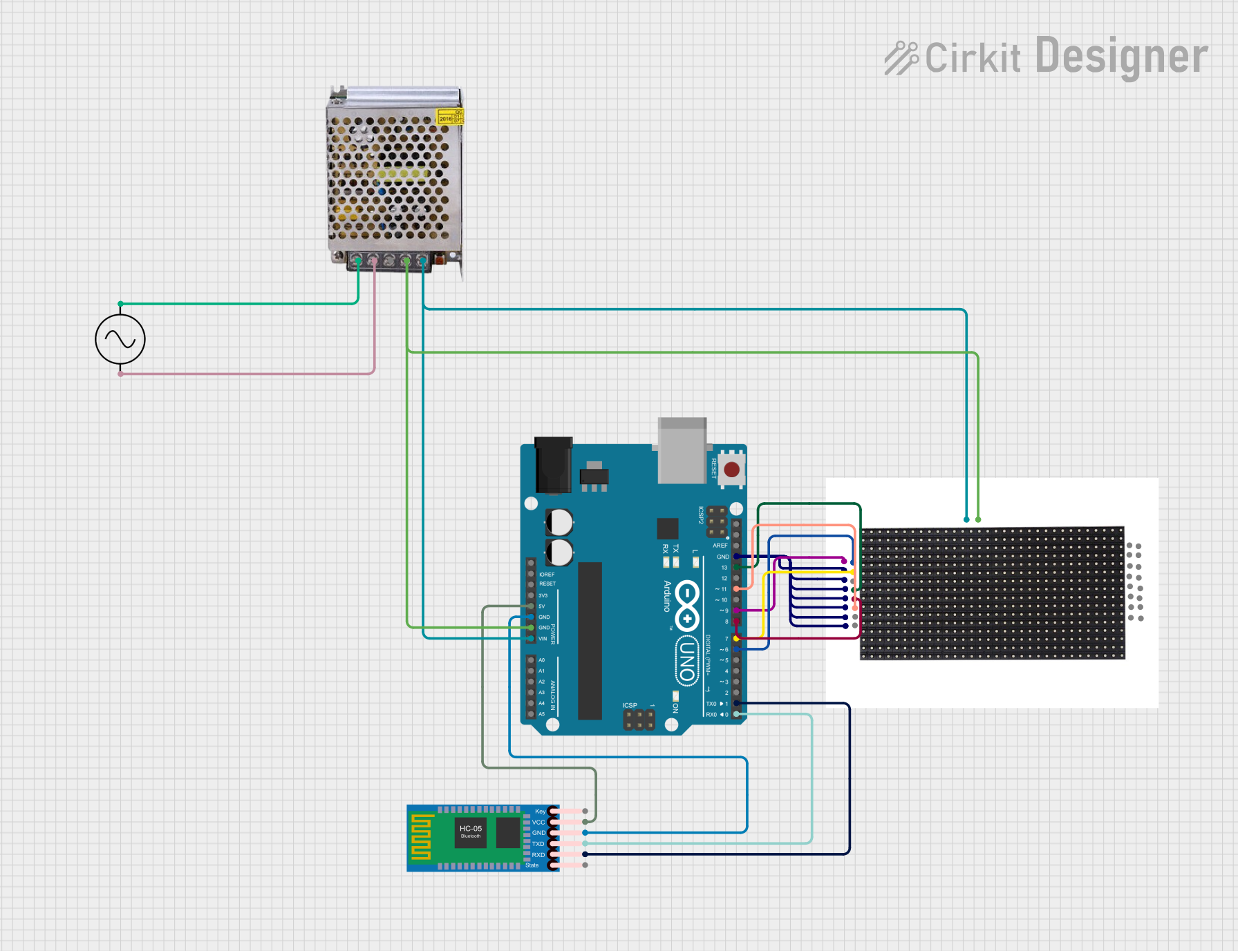
Usage Instructions
How to Use the P5 LED Matrix in a Circuit
- Power Supply: Ensure a stable 5V DC power supply capable of providing sufficient current for the matrix. A single panel may require up to 4A depending on brightness and usage.
- Controller: Use a microcontroller or LED driver board (e.g., Arduino, Raspberry Pi, or ESP32) to control the matrix. The controller must support the HUB75 interface.
- Connections:
- Connect the HUB75 cable from the matrix to the controller.
- Provide 5V and GND connections to the matrix.
- Software: Use libraries such as the
PxMatrixlibrary for Arduino orrpi-rgb-led-matrixfor Raspberry Pi to simplify programming and control.
Example Code for Arduino UNO
Below is an example of how to display text on a P5 LED matrix using the PxMatrix library:
#include <PxMatrix.h>

// Define the display size (adjust based on your matrix resolution)
#define MATRIX_WIDTH 64
#define MATRIX_HEIGHT 32

// Define the pins connected to the HUB75 interface
#define P_LAT 10  // Latch pin
#define P_A   A0  // Row address A
#define P_B   A1  // Row address B
#define P_C   A2  // Row address C
#define P_D   A3  // Row address D
#define P_OE  9   // Output enable pin

// Create a PxMatrix object
PxMatrix display(MATRIX_WIDTH, MATRIX_HEIGHT, P_LAT, P_OE, P_A, P_B, P_C, P_D);

void setup() {
  // Initialize the display
  display.begin(16); // 1/16 scan rate for most P5 matrices
  display.setBrightness(50); // Set brightness (0-255)

  // Display a message
  display.setTextColor(display.color565(255, 0, 0)); // Red text
  display.setCursor(0, 0); // Start at the top-left corner
  display.print("Hello, World!");
}

void loop() {
  // Update the display
  display.display(30); // Refresh rate in milliseconds
}
Important Considerations and Best Practices
- Power Supply: Use a dedicated power supply for the matrix to avoid overloading the microcontroller.
- Heat Management: Ensure proper ventilation as the matrix can generate heat during prolonged use.
- Cable Length: Keep the HUB75 cable as short as possible to minimize signal degradation.
- Brightness: Adjust brightness settings to suit the environment and reduce power consumption.
Troubleshooting and FAQs
Common Issues and Solutions
No Display Output:
- Verify all connections, especially the HUB75 cable and power supply.
- Ensure the microcontroller is programmed correctly and the library is installed.
Flickering or Dim LEDs:
- Check the power supply for sufficient voltage and current.
- Reduce the brightness or refresh rate in the code.
Incorrect Colors or Patterns:
- Ensure the correct matrix type and resolution are defined in the code.
- Verify the data pins are connected to the correct microcontroller pins.
Overheating:
- Reduce brightness or limit the duration of continuous operation.
- Provide adequate ventilation or cooling.
FAQs
Q: Can I chain multiple P5 LED matrices together?
A: Yes, P5 LED matrices are designed to be daisy-chained. Connect the output of one panel to the input of the next and adjust the software settings accordingly.
Q: What is the maximum distance between the controller and the matrix?
A: For reliable operation, keep the distance under 1 meter. Use signal boosters for longer distances.
Q: Can I power the matrix directly from the Arduino?
A: No, the matrix requires more current than the Arduino can provide. Use a dedicated 5V power supply.
By following this documentation, you can effectively integrate and operate a P5 LED matrix in your projects.