Cirkit Designer Logo
Cirkit Designer
Your all-in-one circuit design IDE
Home / 
Component Documentation

How to Use SparkFun MOSFET Power Controller: Examples, Pinouts, and Specs

Image of SparkFun MOSFET Power Controller
Cirkit Designer LogoDesign with SparkFun MOSFET Power Controller in Cirkit Designer

Introduction

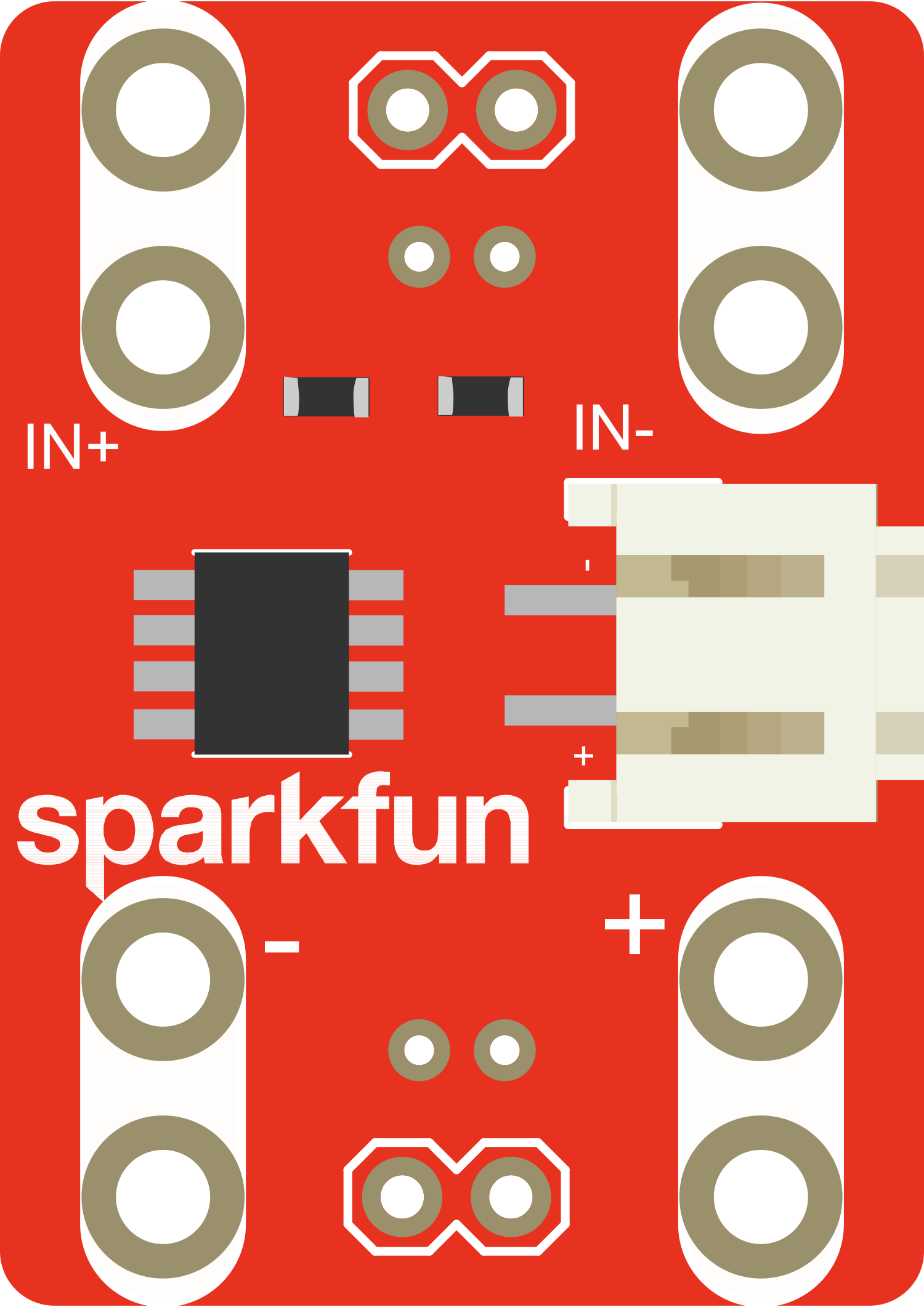
The SparkFun MOSFET Power Controller is a versatile and compact board designed for controlling high-power devices. It utilizes a MOSFET, a type of transistor, to switch large loads with minimal heat generation and power loss. This controller is ideal for applications such as motor control, lighting systems, heating elements, and other scenarios where precise power control is required.

Explore Projects Built with SparkFun MOSFET Power Controller

Use Cirkit Designer to design, explore, and prototype these projects online. Some projects support real-time simulation. Click "Open Project" to start designing instantly!
Pixhawk-Controlled Solenoid Driver with Voltage Regulation
Image of solenoid control circuit: A project utilizing SparkFun MOSFET Power Controller in a practical application
This circuit uses an LM393 comparator to drive an IRFZ44N MOSFET based on the comparison between two input signals from a pixhawk 2.4.8 flight controller. The MOSFET switches a solenoid, with a diode for back EMF protection, and the system is powered by a Lipo battery with voltage regulation provided by a step-up boost converter and a step-down voltage regulator to ensure stable operation. A resistor is connected to the gate of the MOSFET for proper biasing.
Cirkit Designer LogoOpen Project in Cirkit Designer
Dual Motor Control Circuit with LED Indicator and Adjustable Speed
Image of Simple Drone: A project utilizing SparkFun MOSFET Power Controller in a practical application
This circuit is designed to control the speed and direction of coreless motors using MOSFETs, with a potentiometer providing adjustable speed control for one direction. A rocker switch enables power control, and a red LED serves as a power indicator. Diodes are included for motor back-EMF protection.
Cirkit Designer LogoOpen Project in Cirkit Designer
Battery-Powered LM393-Based Voltage Comparator Circuit with MOSFET Control
Image of cut off charger: A project utilizing SparkFun MOSFET Power Controller in a practical application
This circuit is a power regulation and control system that uses an LM393 comparator to monitor voltage levels and control a MOSFET (IRFZ44N) for switching. It is powered by a 12V battery and a USB power source, and includes various resistors and capacitors for filtering and stabilization.
Cirkit Designer LogoOpen Project in Cirkit Designer
ESP32-Controlled Motor with IRFZ44N MOSFET
Image of circit design: A project utilizing SparkFun MOSFET Power Controller in a practical application
This circuit uses an ESP32 microcontroller to control a motor through an IRFZ44N MOSFET. The ESP32's GPIO pin D21 is connected through a 10-ohm resistor to the gate of the MOSFET, which switches the motor on and off. A 10k-ohm pull-down resistor is connected to the gate to ensure the MOSFET turns off when the GPIO pin is not driving it, and the motor is powered by a 12V battery.
Cirkit Designer LogoOpen Project in Cirkit Designer

Explore Projects Built with SparkFun MOSFET Power Controller

Use Cirkit Designer to design, explore, and prototype these projects online. Some projects support real-time simulation. Click "Open Project" to start designing instantly!
Image of solenoid control circuit: A project utilizing SparkFun MOSFET Power Controller in a practical application
Pixhawk-Controlled Solenoid Driver with Voltage Regulation
This circuit uses an LM393 comparator to drive an IRFZ44N MOSFET based on the comparison between two input signals from a pixhawk 2.4.8 flight controller. The MOSFET switches a solenoid, with a diode for back EMF protection, and the system is powered by a Lipo battery with voltage regulation provided by a step-up boost converter and a step-down voltage regulator to ensure stable operation. A resistor is connected to the gate of the MOSFET for proper biasing.
Cirkit Designer LogoOpen Project in Cirkit Designer
Image of Simple Drone: A project utilizing SparkFun MOSFET Power Controller in a practical application
Dual Motor Control Circuit with LED Indicator and Adjustable Speed
This circuit is designed to control the speed and direction of coreless motors using MOSFETs, with a potentiometer providing adjustable speed control for one direction. A rocker switch enables power control, and a red LED serves as a power indicator. Diodes are included for motor back-EMF protection.
Cirkit Designer LogoOpen Project in Cirkit Designer
Image of cut off charger: A project utilizing SparkFun MOSFET Power Controller in a practical application
Battery-Powered LM393-Based Voltage Comparator Circuit with MOSFET Control
This circuit is a power regulation and control system that uses an LM393 comparator to monitor voltage levels and control a MOSFET (IRFZ44N) for switching. It is powered by a 12V battery and a USB power source, and includes various resistors and capacitors for filtering and stabilization.
Cirkit Designer LogoOpen Project in Cirkit Designer
Image of circit design: A project utilizing SparkFun MOSFET Power Controller in a practical application
ESP32-Controlled Motor with IRFZ44N MOSFET
This circuit uses an ESP32 microcontroller to control a motor through an IRFZ44N MOSFET. The ESP32's GPIO pin D21 is connected through a 10-ohm resistor to the gate of the MOSFET, which switches the motor on and off. A 10k-ohm pull-down resistor is connected to the gate to ensure the MOSFET turns off when the GPIO pin is not driving it, and the motor is powered by a 12V battery.
Cirkit Designer LogoOpen Project in Cirkit Designer

Common Applications and Use Cases

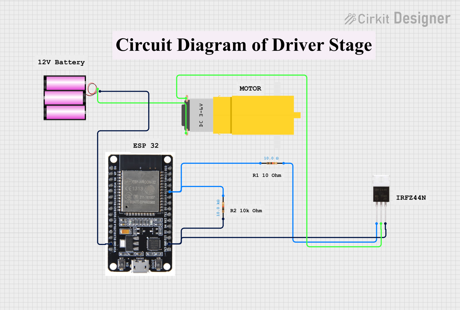
  • Robotics: Controlling DC motors for movement and positioning.
  • Home Automation: Managing high-power LEDs or smart lighting systems.
  • Industrial Control: Operating solenoids, pumps, or valves.
  • DIY Projects: Power management in custom builds and prototypes.

Technical Specifications

Key Technical Details

  • Operating Voltage (Vcc): 3.3V to 5V
  • Output Voltage (Vdss): Up to 30V
  • Continuous Current (Id): Up to 6A (with proper heat sinking)
  • Pulse Current (Idm): Up to 20A (pulsed)
  • Logic Level Threshold: Compatible with 3.3V and 5V logic levels
  • Rds(on): Low on-resistance for efficient switching

Pin Configuration and Descriptions

Pin Number Name Description
1 GND Ground connection for the logic/control side
2 IN Logic-level input to control the MOSFET gate
3 Vcc Supply voltage for the logic/control side (3.3V to 5V)
4 V+ Power supply input for the load (up to 30V)
5 OUT Output to the load, switched by the MOSFET

Usage Instructions

How to Use the Component in a Circuit

  1. Power Supply Connection: Connect the power supply for the load to the V+ and GND pins. Ensure the voltage does not exceed the maximum rating of 30V.
  2. Load Connection: Attach the high-power device you wish to control to the OUT pin and GND.
  3. Control Signal: Connect the IN pin to a PWM-capable pin on a microcontroller, such as an Arduino UNO, to control the MOSFET gate.
  4. Logic Power Supply: Provide 3.3V or 5V to the Vcc pin from the microcontroller to power the logic side of the board.

Important Considerations and Best Practices

  • Heat Management: For continuous high-current applications, attach a heat sink to the MOSFET to prevent overheating.
  • PWM Frequency: Choose an appropriate PWM frequency to avoid audible noise in applications like motor control.
  • Gate Protection: Ensure that the voltage on the IN pin does not exceed the Vcc voltage to protect the MOSFET gate.

Example Code for Arduino UNO

// Define the MOSFET gate control pin
const int mosfetPin = 3; // Connect to the IN pin of the MOSFET Power Controller

void setup() {
  // Set the MOSFET control pin as an output
  pinMode(mosfetPin, OUTPUT);
}

void loop() {
  // Turn on the MOSFET (connect OUT to GND)
  digitalWrite(mosfetPin, HIGH);
  delay(1000); // Keep the MOSFET on for 1 second

  // Turn off the MOSFET (disconnect OUT from GND)
  digitalWrite(mosfetPin, LOW);
  delay(1000); // Keep the MOSFET off for 1 second
}

Troubleshooting and FAQs

Common Issues Users Might Face

  • MOSFET Not Switching: Ensure that the logic-level voltage at the IN pin is sufficient to fully turn on the MOSFET.
  • Overheating: If the MOSFET is overheating, check the current draw and attach a heat sink if necessary.
  • Load Not Powering On: Verify that the power supply is connected correctly and that the voltage and current ratings are within the specified limits.

Solutions and Tips for Troubleshooting

  • Check Connections: Double-check all connections, including power supply, load, and control signal wires.
  • Use a Multimeter: Measure the voltage at the IN pin to ensure it's within the logic-level range.
  • PWM Duty Cycle: Adjust the PWM duty cycle to control the average power delivered to the load.

FAQs

Q: Can I use the SparkFun MOSFET Power Controller with a 3.3V microcontroller? A: Yes, the controller is compatible with both 3.3V and 5V logic levels.

Q: What is the maximum current the MOSFET can handle? A: The MOSFET can handle up to 6A continuously with proper heat sinking and up to 20A in pulses.

Q: How do I control the speed of a motor with this MOSFET? A: You can control the motor speed by applying a PWM signal to the IN pin and adjusting the duty cycle.

This documentation provides a comprehensive guide to using the SparkFun MOSFET Power Controller. For further assistance or technical support, please contact SparkFun's customer service or visit their online forums.