How to Use DC power supply adapter: Examples, Pinouts, and Specs
Introduction
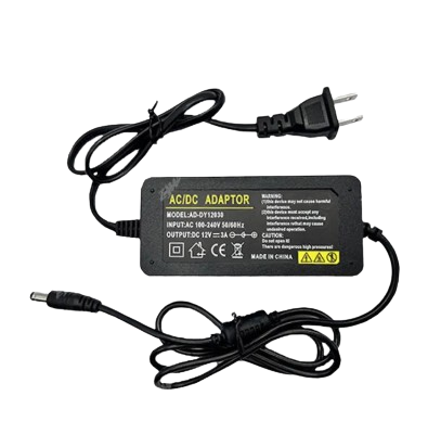
A DC power supply adapter is a device that converts alternating current (AC) voltage from a wall outlet into a stable direct current (DC) voltage. It is widely used to power electronic devices that require a specific DC voltage for operation. These adapters are available in various voltage and current ratings to suit different applications.
Explore Projects Built with DC power supply adapter


Explore Projects Built with DC power supply adapter
Common Applications and Use Cases
- Powering microcontrollers, such as Arduino boards and Raspberry Pi devices
- Supplying power to consumer electronics like routers, modems, and LED strips
- Charging batteries for portable devices
- Providing power to small motors and sensors in DIY projects
Technical Specifications
Below are the general technical specifications for a typical DC power supply adapter. Always refer to the specific datasheet or label on your adapter for exact details.
Key Technical Details
- Input Voltage: 100-240V AC, 50/60Hz (varies by region)
- Output Voltage: Common values include 5V, 9V, 12V, 24V DC
- Output Current: Ranges from 0.5A to 5A or higher, depending on the model
- Polarity: Typically center-positive (verify before use)
- Connector Type: Barrel jack (e.g., 5.5mm outer diameter, 2.1mm inner diameter)
Pin Configuration and Descriptions
The DC power supply adapter typically has a barrel connector with the following pin configuration:
| Pin Name | Description |
|---|---|
| Outer Sleeve | Ground (GND) |
| Inner Pin | Positive DC voltage (V+) |
Note: Always confirm the polarity of your adapter and the device it powers to avoid damage.
Usage Instructions
How to Use the Component in a Circuit
- Verify Voltage and Current Requirements: Ensure the adapter's output voltage and current match the requirements of your device.
- Check Polarity: Confirm that the adapter's polarity matches the input polarity of your device (e.g., center-positive or center-negative).
- Connect to the Device: Plug the barrel connector into the device's power input jack.
- Power On: Plug the adapter into a wall outlet and turn on the device.
Important Considerations and Best Practices
- Avoid Overloading: Do not exceed the adapter's rated current output, as this may cause overheating or failure.
- Use a Voltage Regulator: If your circuit requires a lower voltage than the adapter provides, use a voltage regulator to step down the voltage.
- Check for Noise: Some adapters may introduce electrical noise. Use capacitors or filters if noise affects your circuit.
- Disconnect When Not in Use: Unplug the adapter when not in use to conserve energy and prevent overheating.
Example: Using a DC Power Supply Adapter with an Arduino UNO
To power an Arduino UNO with a 12V DC adapter:
- Connect the barrel jack of the adapter to the Arduino's power input port.
- Ensure the adapter provides 12V DC and at least 500mA of current.
- Plug the adapter into a wall outlet. The Arduino will power on automatically.
Alternatively, you can use the adapter to power the Arduino through the VIN pin. Below is an example circuit and code to blink an LED:
Circuit Setup
- Connect the adapter's positive output to the Arduino's VIN pin.
- Connect the adapter's ground output to the Arduino's GND pin.
- Connect an LED to pin 13 with a 220-ohm resistor in series.
Arduino Code
// Simple LED blink example
// This code blinks an LED connected to pin 13 of the Arduino UNO

void setup() {
  pinMode(13, OUTPUT); // Set pin 13 as an output
}

void loop() {
  digitalWrite(13, HIGH); // Turn the LED on
  delay(1000);            // Wait for 1 second
  digitalWrite(13, LOW);  // Turn the LED off
  delay(1000);            // Wait for 1 second
}
Troubleshooting and FAQs
Common Issues Users Might Face
Device Not Powering On:
- Check if the adapter is plugged into a working wall outlet.
- Verify that the adapter's output voltage matches the device's requirements.
- Ensure the barrel connector is securely connected to the device.
Overheating Adapter:
- Ensure the device's current draw does not exceed the adapter's rated output.
- Check for short circuits in the connected device or circuit.
Electrical Noise in Circuit:
- Add decoupling capacitors (e.g., 0.1µF and 10µF) near the power input of your circuit.
- Use a higher-quality adapter with better filtering.
Incorrect Polarity:
- Verify the polarity of the adapter and the device before connecting. Using a multimeter can help confirm this.
Solutions and Tips for Troubleshooting
- Use a Multimeter: Measure the adapter's output voltage and polarity to ensure it matches the device's requirements.
- Inspect the Connector: Check for physical damage or loose connections in the barrel jack.
- Test with Another Device: Use the adapter with a different device to confirm it is functioning properly.
By following these guidelines, you can safely and effectively use a DC power supply adapter in your projects.