Cirkit Designer Logo
Cirkit Designer
Your all-in-one circuit design IDE
Home / 
Component Documentation

How to Use Solar charge controller: Examples, Pinouts, and Specs
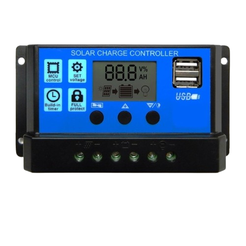

Image of Solar charge controller
Cirkit Designer LogoDesign with Solar charge controller in Cirkit Designer

Introduction

A solar charge controller is a critical component in solar power systems. It regulates the voltage and current coming from a solar panel to a battery, ensuring optimal charging and preventing overcharging. By managing the energy flow, it protects the battery from damage and extends its lifespan. Solar charge controllers are commonly used in off-grid solar systems, RVs, boats, and remote power setups.

Explore Projects Built with Solar charge controller
Use Cirkit Designer to design, explore, and prototype these projects online. Some projects support real-time simulation. Click "Open Project" to start designing instantly!
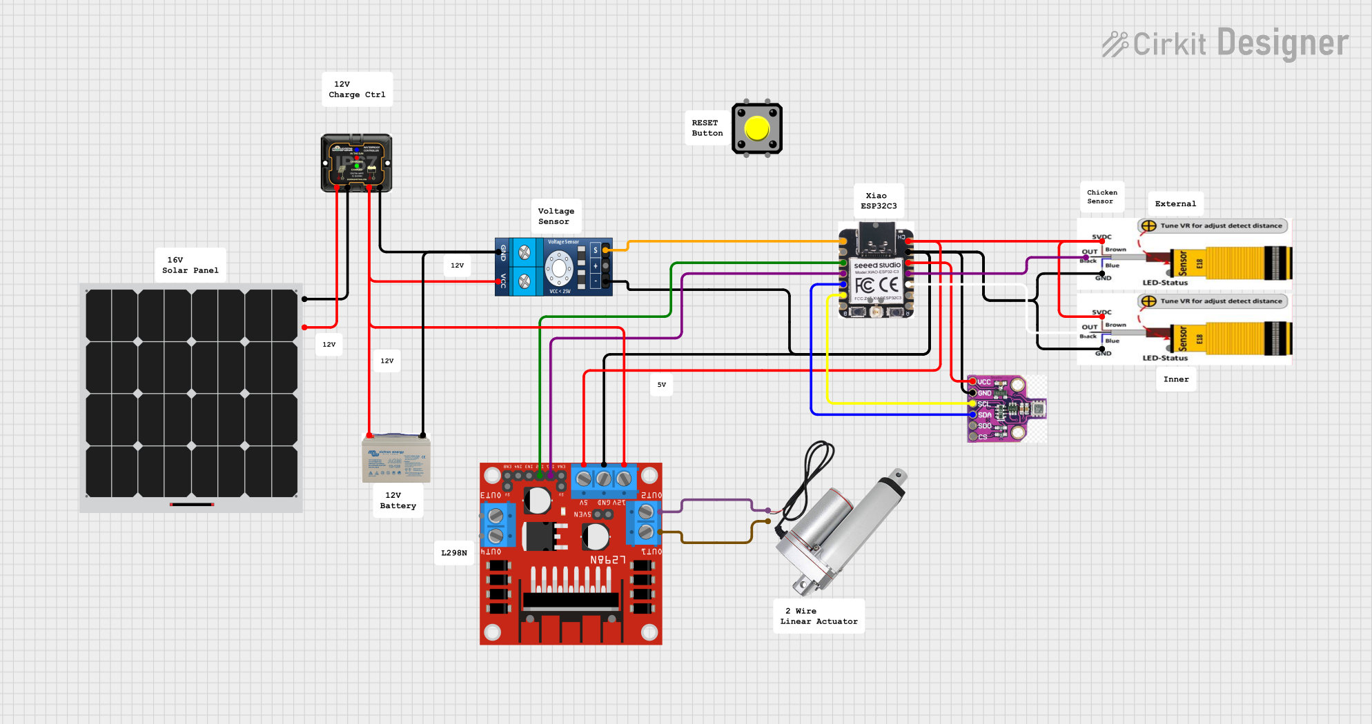
Solar-Powered Linear Actuator System with ESP32 and Sensor Integration
Image of Chicken Coup Automatic Door: A project utilizing Solar charge controller in a practical application
This circuit is a solar-powered system that charges a 12V AGM battery using an MPPT charge controller connected to a solar panel. It includes a Xiao ESP32C3 microcontroller that monitors environmental data via a BME680 sensor and controls a linear actuator through an L298N motor driver, with additional input from IR sensors and a voltage sensor.
Cirkit Designer LogoOpen Project in Cirkit Designer
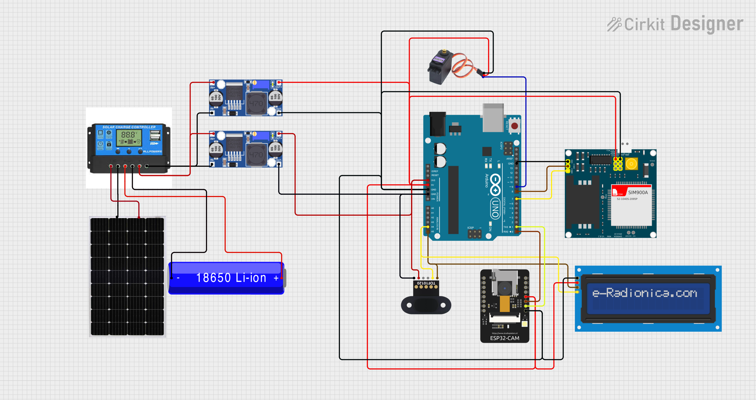
Solar-Powered IoT Device with ESP32-CAM, SIM900A GSM, and TOF Sensor Integration
Image of mouse trap: A project utilizing Solar charge controller in a practical application
This circuit appears to be a solar-powered system with a charge controller connected to a solar panel and a Li-ion battery, managing power distribution. The Arduino UNO microcontroller is interfaced with an ESP32-CAM, SIM900A GSM module, TOF10120 range sensor, MG996R servo, and an I2C LCD screen, likely for monitoring and control purposes. Buck converters are used to regulate voltage for the microcontroller and peripherals, ensuring stable operation.
Cirkit Designer LogoOpen Project in Cirkit Designer
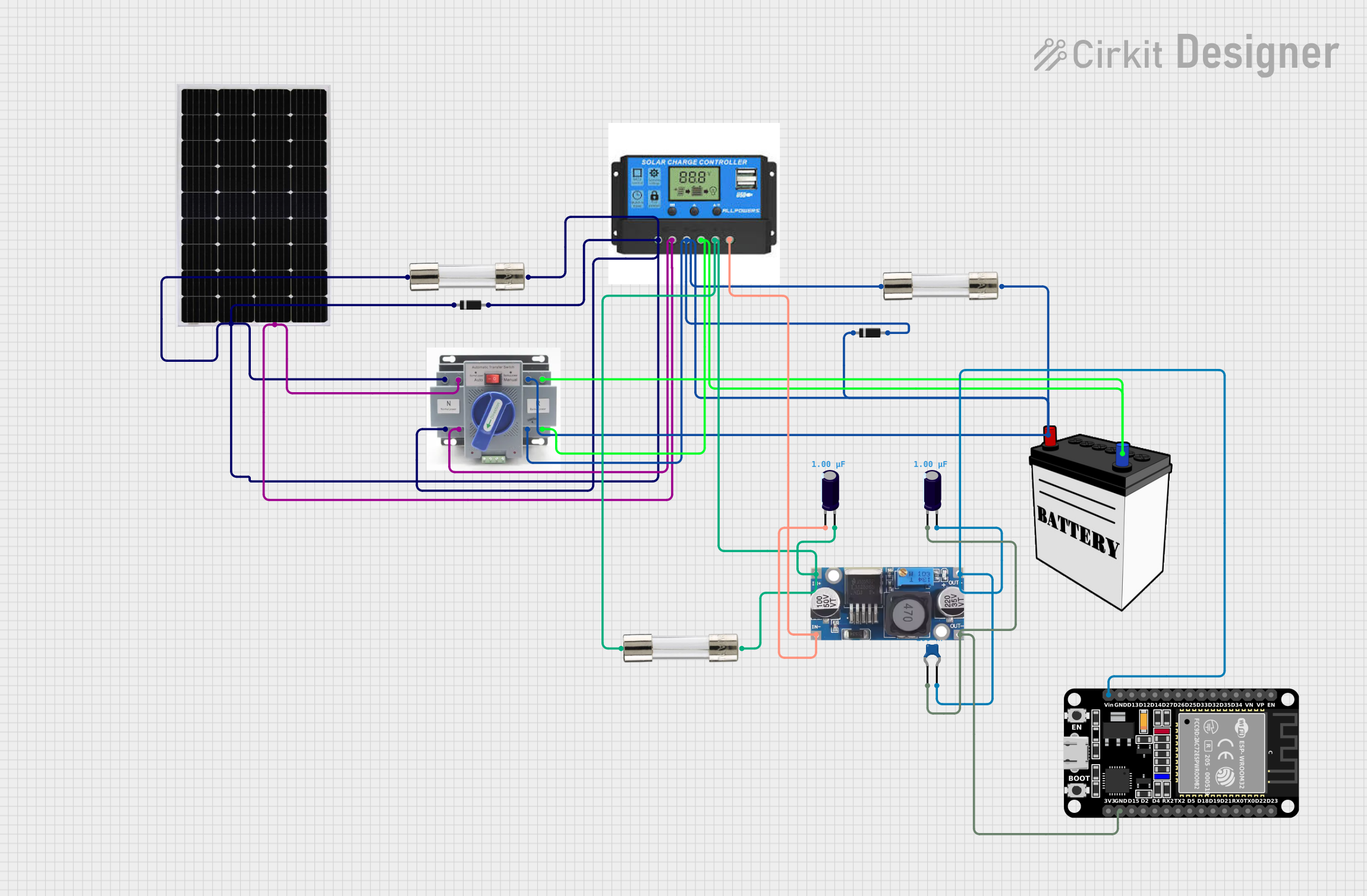
Solar-Powered ESP32 IoT Device with Battery Backup and Power Management
Image of power supply ni kuya rey: A project utilizing Solar charge controller in a practical application
This is a solar power management circuit that uses a charge controller to regulate the charging of a 12V battery from a solar panel and provides a stabilized voltage output to a load via a step-down buck converter. Safety features include diodes for reverse current protection and fuses for overcurrent protection, while capacitors ensure voltage stability for the connected load. An ESP32 microcontroller is included for potential control or monitoring functions.
Cirkit Designer LogoOpen Project in Cirkit Designer
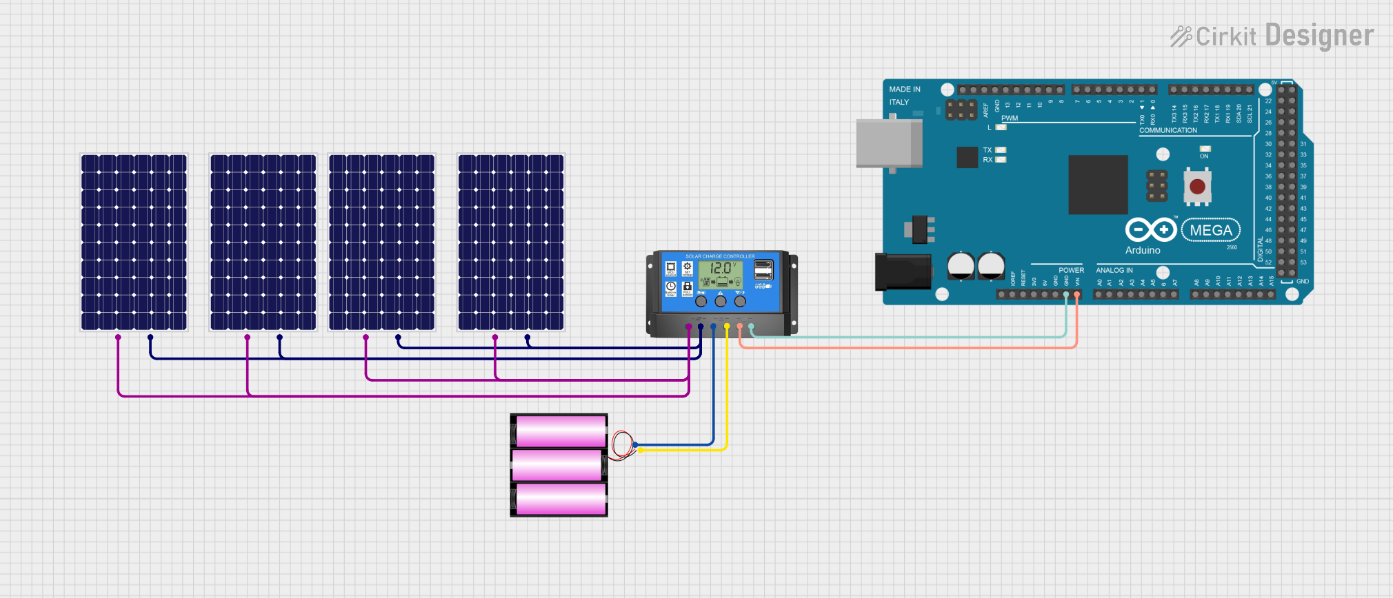
Solar-Powered Battery Charging System with Arduino Mega 2560
Image of solar 1: A project utilizing Solar charge controller in a practical application
This circuit is a solar power management system that uses multiple solar panels to charge a 12V battery via a solar charge controller. The charge controller also powers an Arduino Mega 2560, which can be used for further processing or control tasks.
Cirkit Designer LogoOpen Project in Cirkit Designer

Explore Projects Built with Solar charge controller

Use Cirkit Designer to design, explore, and prototype these projects online. Some projects support real-time simulation. Click "Open Project" to start designing instantly!
Image of Chicken Coup Automatic Door: A project utilizing Solar charge controller in a practical application
Solar-Powered Linear Actuator System with ESP32 and Sensor Integration
This circuit is a solar-powered system that charges a 12V AGM battery using an MPPT charge controller connected to a solar panel. It includes a Xiao ESP32C3 microcontroller that monitors environmental data via a BME680 sensor and controls a linear actuator through an L298N motor driver, with additional input from IR sensors and a voltage sensor.
Cirkit Designer LogoOpen Project in Cirkit Designer
Image of mouse trap: A project utilizing Solar charge controller in a practical application
Solar-Powered IoT Device with ESP32-CAM, SIM900A GSM, and TOF Sensor Integration
This circuit appears to be a solar-powered system with a charge controller connected to a solar panel and a Li-ion battery, managing power distribution. The Arduino UNO microcontroller is interfaced with an ESP32-CAM, SIM900A GSM module, TOF10120 range sensor, MG996R servo, and an I2C LCD screen, likely for monitoring and control purposes. Buck converters are used to regulate voltage for the microcontroller and peripherals, ensuring stable operation.
Cirkit Designer LogoOpen Project in Cirkit Designer
Image of power supply ni kuya rey: A project utilizing Solar charge controller in a practical application
Solar-Powered ESP32 IoT Device with Battery Backup and Power Management
This is a solar power management circuit that uses a charge controller to regulate the charging of a 12V battery from a solar panel and provides a stabilized voltage output to a load via a step-down buck converter. Safety features include diodes for reverse current protection and fuses for overcurrent protection, while capacitors ensure voltage stability for the connected load. An ESP32 microcontroller is included for potential control or monitoring functions.
Cirkit Designer LogoOpen Project in Cirkit Designer
Image of solar 1: A project utilizing Solar charge controller in a practical application
Solar-Powered Battery Charging System with Arduino Mega 2560
This circuit is a solar power management system that uses multiple solar panels to charge a 12V battery via a solar charge controller. The charge controller also powers an Arduino Mega 2560, which can be used for further processing or control tasks.
Cirkit Designer LogoOpen Project in Cirkit Designer

Common Applications and Use Cases

  • Off-grid solar power systems
  • Solar-powered lighting systems
  • RVs, boats, and caravans
  • Remote monitoring stations
  • Backup power systems

Technical Specifications

Below are the general technical specifications for a typical solar charge controller. Always refer to the specific datasheet for your model.

Key Technical Details

  • Input Voltage Range: 12V/24V auto-detect (some models support up to 48V)
  • Maximum Input Current: 10A, 20A, 30A, or higher (depending on the model)
  • Battery Voltage: 12V/24V (auto-detect)
  • Charging Technology: PWM (Pulse Width Modulation) or MPPT (Maximum Power Point Tracking)
  • Operating Temperature: -20°C to +60°C
  • Efficiency: Up to 98% (for MPPT models)
  • Load Control: Overload, short circuit, and reverse polarity protection

Pin Configuration and Descriptions

The solar charge controller typically has the following terminals:

Pin/Terminal Label Description
1 Solar Panel (+) Positive terminal for connecting the solar panel
2 Solar Panel (-) Negative terminal for connecting the solar panel
3 Battery (+) Positive terminal for connecting the battery
4 Battery (-) Negative terminal for connecting the battery
5 Load (+) Positive terminal for connecting the DC load (e.g., lights, fans)
6 Load (-) Negative terminal for connecting the DC load
7 USB Output USB port for charging small devices (available on some models)
8 Communication Optional port for monitoring or configuring the controller (e.g., RS485, UART)

Usage Instructions

How to Use the Solar Charge Controller in a Circuit

  1. Connect the Battery First: Always connect the battery to the charge controller before connecting the solar panel or load. This ensures the controller detects the correct system voltage.
  2. Connect the Solar Panel: Attach the solar panel's positive and negative terminals to the corresponding inputs on the charge controller.
  3. Connect the Load: If you are powering DC devices directly, connect them to the load terminals on the controller.
  4. Monitor the System: Use the controller's display or monitoring software (if available) to check the system's status, including battery voltage, charging current, and load status.

Important Considerations and Best Practices

  • Battery Type: Ensure the charge controller is compatible with your battery type (e.g., lead-acid, lithium-ion).
  • System Voltage: Verify that the controller supports the voltage of your solar panel and battery.
  • Placement: Install the controller in a well-ventilated area to prevent overheating.
  • Wiring: Use appropriately sized wires to handle the current without excessive voltage drop.
  • Fuses: Add fuses or circuit breakers between the solar panel, battery, and controller for safety.

Example Code for Arduino UNO Integration

If your solar charge controller supports communication (e.g., via RS485 or UART), you can monitor its data using an Arduino UNO. Below is an example code snippet for reading data from a controller with an RS485 interface:

#include <SoftwareSerial.h>

// Define RS485 communication pins
#define RX_PIN 10  // Arduino pin connected to RS485 module's RO (Receive Out)
#define TX_PIN 11  // Arduino pin connected to RS485 module's DI (Data In)
#define DE_PIN 8   // Arduino pin connected to RS485 module's DE (Driver Enable)
#define RE_PIN 9   // Arduino pin connected to RS485 module's RE (Receiver Enable)

SoftwareSerial rs485Serial(RX_PIN, TX_PIN);

void setup() {
  pinMode(DE_PIN, OUTPUT);
  pinMode(RE_PIN, OUTPUT);

  // Initialize RS485 communication
  digitalWrite(DE_PIN, LOW); // Disable driver
  digitalWrite(RE_PIN, LOW); // Enable receiver
  rs485Serial.begin(9600);   // Set baud rate to match the controller

  Serial.begin(9600);        // For debugging via Serial Monitor
  Serial.println("RS485 Communication Initialized");
}

void loop() {
  // Request data from the solar charge controller
  digitalWrite(DE_PIN, HIGH); // Enable driver
  digitalWrite(RE_PIN, HIGH); // Disable receiver
  rs485Serial.write(0x01);    // Example request (modify based on controller protocol)
  delay(10);
  digitalWrite(DE_PIN, LOW);  // Disable driver
  digitalWrite(RE_PIN, LOW);  // Enable receiver

  // Read response from the controller
  if (rs485Serial.available()) {
    Serial.print("Controller Response: ");
    while (rs485Serial.available()) {
      Serial.print(rs485Serial.read(), HEX);
      Serial.print(" ");
    }
    Serial.println();
  }

  delay(1000); // Wait before sending the next request
}

Note: Refer to your solar charge controller's communication protocol for the correct request and response format.

Troubleshooting and FAQs

Common Issues and Solutions

  1. Controller Not Powering On

    • Cause: Battery not connected or insufficient voltage.
    • Solution: Ensure the battery is properly connected and has sufficient charge.
  2. No Charging from Solar Panel

    • Cause: Incorrect wiring or insufficient sunlight.
    • Solution: Verify the solar panel connections and ensure it is exposed to direct sunlight.
  3. Load Not Working

    • Cause: Load exceeds the controller's rated capacity or is improperly connected.
    • Solution: Check the load rating and connections. Reduce the load if necessary.
  4. Overheating

    • Cause: Poor ventilation or excessive current.
    • Solution: Install the controller in a well-ventilated area and ensure the current is within limits.

FAQs

  • Q: Can I use the controller without a battery?
    A: No, most solar charge controllers require a battery to function properly.

  • Q: How do I know if the controller is working?
    A: Check the LED indicators or display (if available) for charging and load status.

  • Q: Can I connect multiple solar panels?
    A: Yes, but ensure the combined voltage and current do not exceed the controller's ratings.

  • Q: What is the difference between PWM and MPPT controllers?
    A: MPPT controllers are more efficient as they maximize the power output from the solar panel, especially in varying sunlight conditions. PWM controllers are simpler and more cost-effective but less efficient.

By following this documentation, you can effectively use and troubleshoot your solar charge controller for optimal performance in your solar power system.