How to Use ESP32D on Goouuu Expansion Board: Examples, Pinouts, and Specs
Introduction
The ESP32D on the Goouuu Expansion Board is a versatile development platform designed by Espressif for Internet of Things (IoT) applications. It features the ESP32D microcontroller, which is known for its dual-core processor, integrated Wi-Fi, and Bluetooth capabilities. The Goouuu Expansion Board enhances the ESP32D by providing additional GPIO pins, onboard sensors, and connectivity options, making it ideal for rapid prototyping and integration into IoT projects.
Explore Projects Built with ESP32D on Goouuu Expansion Board

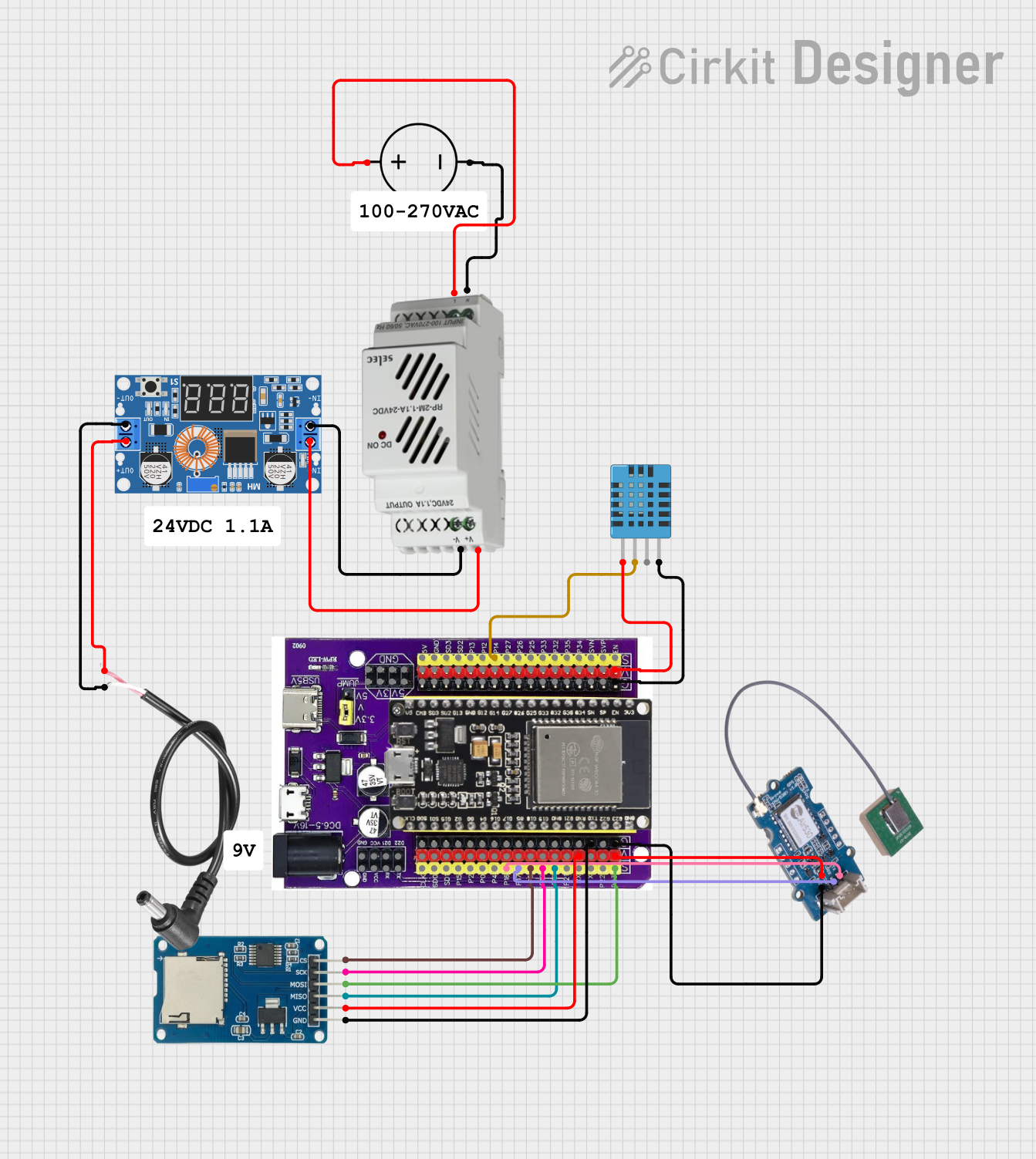
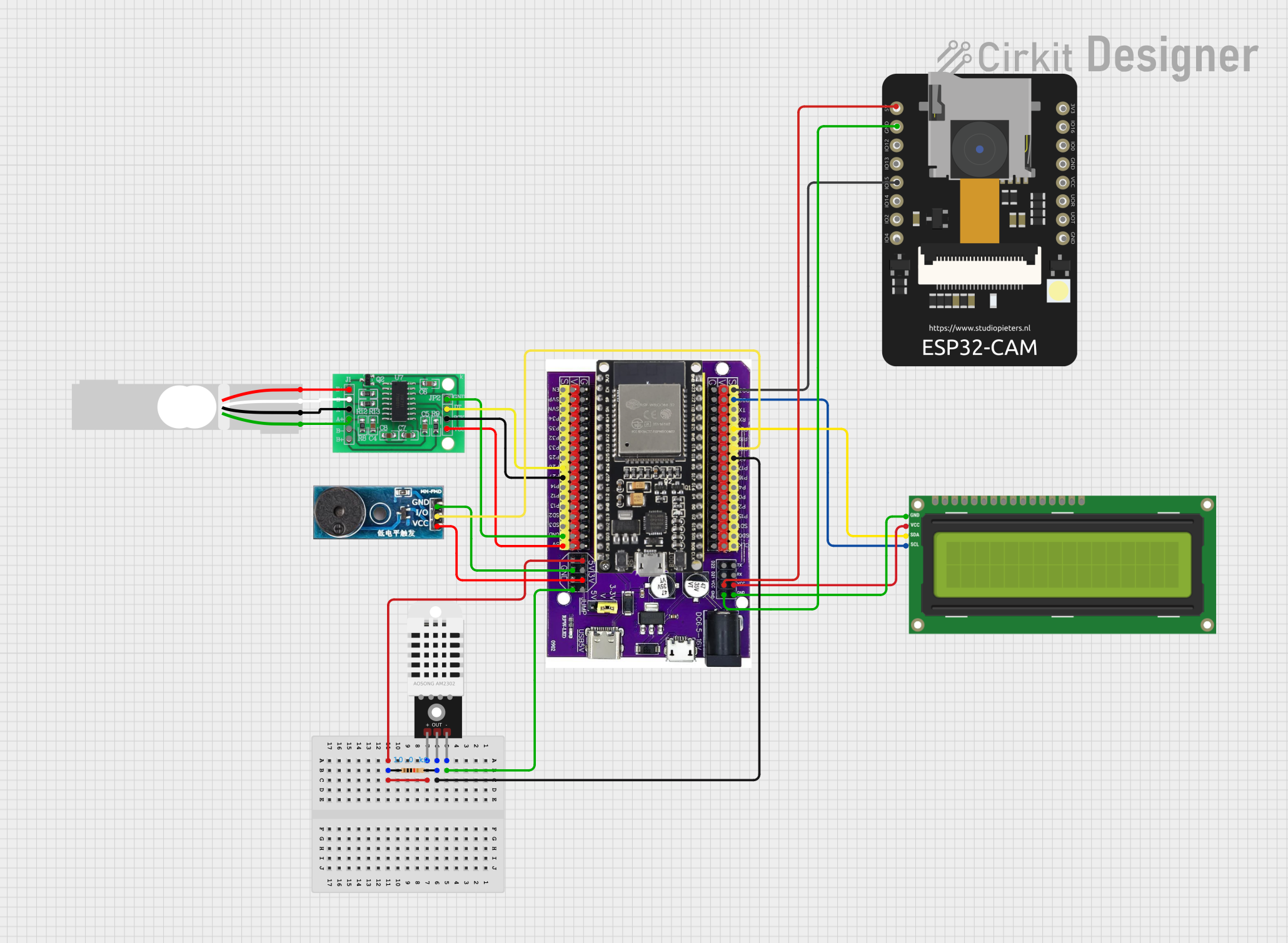
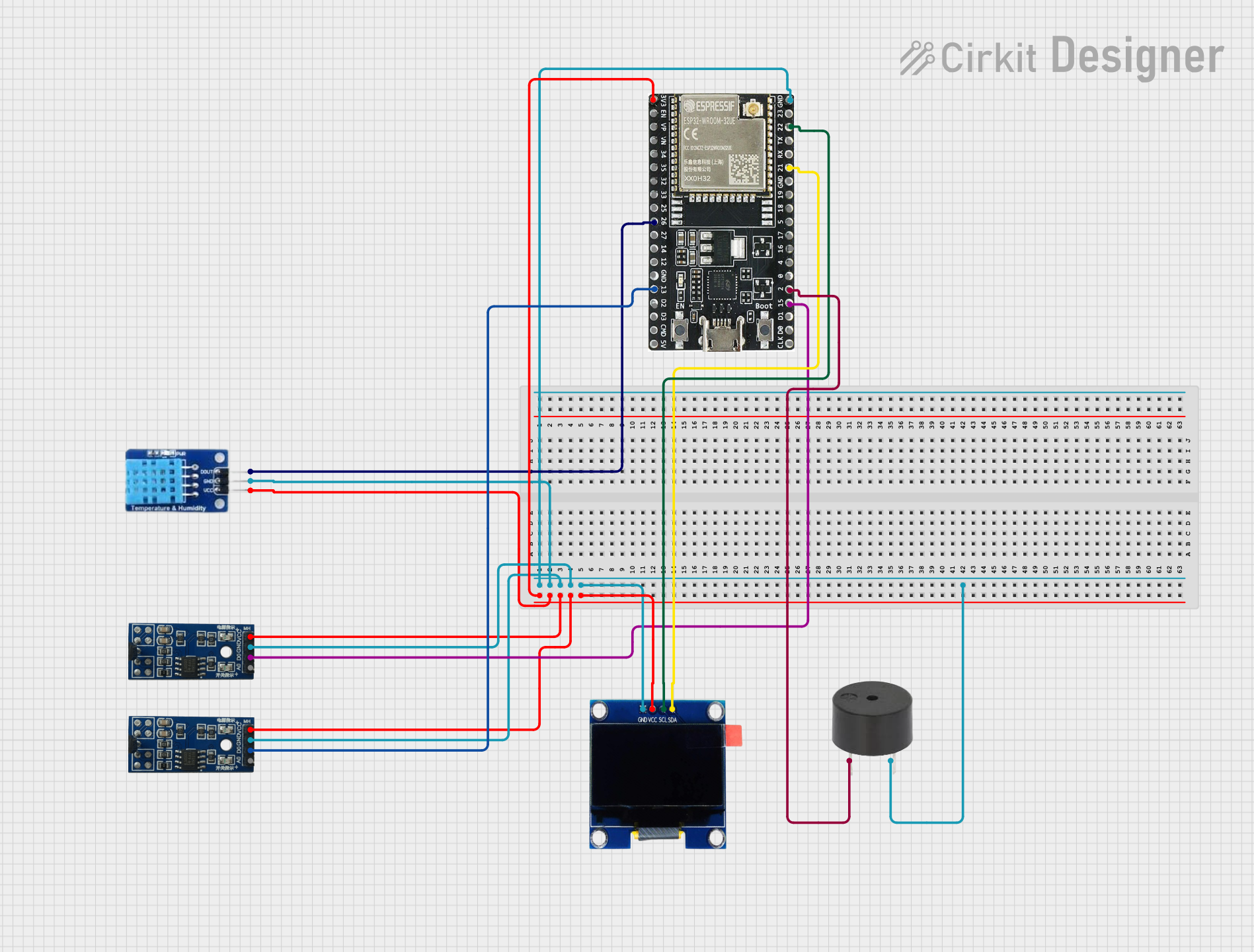
Explore Projects Built with ESP32D on Goouuu Expansion Board
Common Applications and Use Cases
- Smart home automation systems
- Industrial IoT monitoring and control
- Wearable devices
- Wireless sensor networks
- Robotics and embedded systems
- Educational and prototyping projects
Technical Specifications
Key Technical Details
| Parameter | Value |
|---|---|
| Microcontroller | ESP32D (Espressif) |
| Processor | Dual-core Xtensa® 32-bit LX6 @ 240 MHz |
| Flash Memory | 4 MB (onboard) |
| SRAM | 520 KB |
| Wireless Connectivity | Wi-Fi 802.11 b/g/n, Bluetooth v4.2 + BLE |
| Operating Voltage | 3.3V |
| Input Voltage (VIN) | 5V (via USB or external power supply) |
| GPIO Pins | 30+ (including ADC, DAC, PWM, I2C, SPI) |
| Onboard Sensors | Temperature and humidity sensor |
| USB Interface | Micro-USB for programming and power |
| Dimensions | 60mm x 30mm |
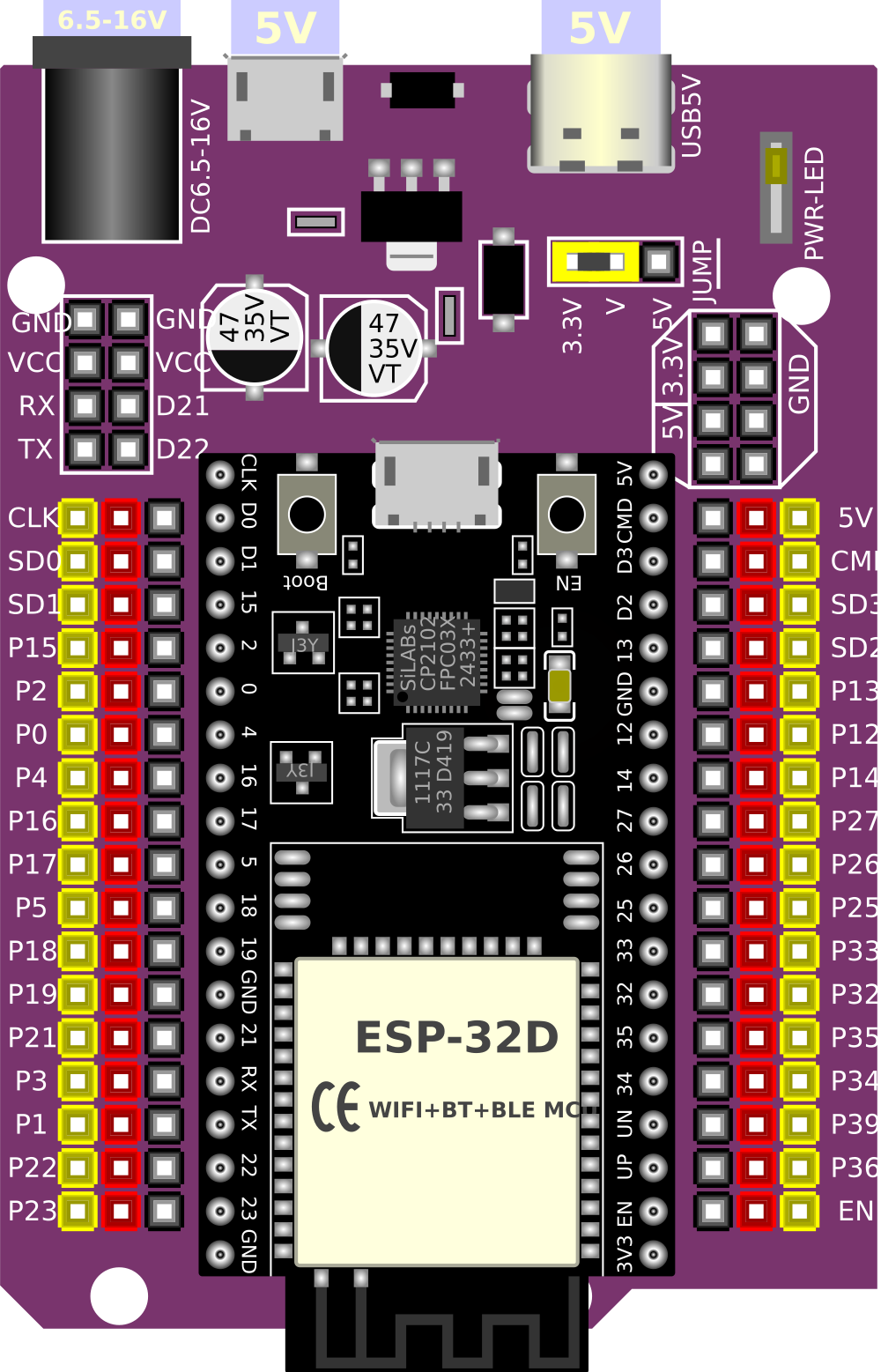
Pin Configuration and Descriptions
The Goouuu Expansion Board provides access to the ESP32D's GPIO pins and additional features. Below is the pinout description:
| Pin Name | Pin Number | Functionality |
|---|---|---|
| VIN | - | Input voltage (5V) |
| GND | - | Ground |
| 3V3 | - | 3.3V output |
| GPIO0 | 0 | General-purpose I/O, boot mode selection |
| GPIO1 | 1 | UART TX |
| GPIO2 | 2 | General-purpose I/O, ADC, PWM |
| GPIO3 | 3 | UART RX |
| GPIO4 | 4 | General-purpose I/O, ADC, PWM |
| GPIO5 | 5 | General-purpose I/O, ADC, PWM |
| GPIO12 | 12 | General-purpose I/O, ADC, PWM |
| GPIO13 | 13 | General-purpose I/O, ADC, PWM |
| GPIO14 | 14 | General-purpose I/O, ADC, PWM |
| GPIO15 | 15 | General-purpose I/O, ADC, PWM |
| GPIO16 | 16 | General-purpose I/O |
| GPIO17 | 17 | General-purpose I/O |
| ADC1 | - | 12-bit ADC (up to 18 channels) |
| DAC1 | - | 8-bit DAC |
| I2C SDA | - | I2C data line |
| I2C SCL | - | I2C clock line |
| SPI MOSI | - | SPI data out |
| SPI MISO | - | SPI data in |
| SPI CLK | - | SPI clock |
| SPI CS | - | SPI chip select |
Usage Instructions
How to Use the Component in a Circuit
- Powering the Board: Connect the board to a 5V power source using the micro-USB port or the VIN pin.
- Programming: Use the micro-USB port to upload code to the ESP32D using the Arduino IDE or Espressif's ESP-IDF.
- Connecting Peripherals: Use the GPIO pins to connect sensors, actuators, or other peripherals. Ensure the voltage levels are compatible (3.3V logic).
- Wi-Fi and Bluetooth: Configure the wireless connectivity in your code to enable communication with other devices or networks.
Important Considerations and Best Practices
- Voltage Levels: The ESP32D operates at 3.3V logic. Avoid connecting 5V signals directly to the GPIO pins.
- Boot Mode: GPIO0 is used for boot mode selection. Ensure it is not pulled low during normal operation.
- Power Supply: Use a stable power source to avoid unexpected resets or instability.
- Heat Management: The ESP32D may heat up during operation. Ensure proper ventilation if used in enclosed spaces.
Example Code for Arduino UNO Integration
Below is an example of how to use the ESP32D with the Arduino IDE to connect to a Wi-Fi network and blink an LED:
#include <WiFi.h> // Include the Wi-Fi library

// Replace with your network credentials
const char* ssid = "Your_SSID";
const char* password = "Your_PASSWORD";

const int ledPin = 2; // GPIO2 is connected to the onboard LED

void setup() {
  pinMode(ledPin, OUTPUT); // Set GPIO2 as an output
  Serial.begin(115200);    // Start the serial communication

  // Connect to Wi-Fi
  Serial.print("Connecting to Wi-Fi");
  WiFi.begin(ssid, password);
  while (WiFi.status() != WL_CONNECTED) {
    delay(500);
    Serial.print(".");
  }
  Serial.println("\nWi-Fi connected!");
}

void loop() {
  digitalWrite(ledPin, HIGH); // Turn the LED on
  delay(1000);                // Wait for 1 second
  digitalWrite(ledPin, LOW);  // Turn the LED off
  delay(1000);                // Wait for 1 second
}
Troubleshooting and FAQs
Common Issues Users Might Face
Board Not Detected by Computer:
- Ensure the USB cable is functional and supports data transfer.
- Install the correct USB-to-serial driver for the ESP32D.
Wi-Fi Connection Fails:
- Double-check the SSID and password in your code.
- Ensure the Wi-Fi network is within range and operational.
GPIO Pin Not Working:
- Verify the pin configuration in your code.
- Check for conflicting pin usage (e.g., GPIO0 for boot mode).
Program Upload Fails:
- Ensure the correct board and port are selected in the Arduino IDE.
- Press and hold the "BOOT" button on the board during the upload process.
Solutions and Tips for Troubleshooting
- Serial Monitor Debugging: Use the Serial Monitor in the Arduino IDE to print debug messages and identify issues.
- Power Supply Check: Ensure the board is receiving sufficient power, especially when using Wi-Fi or Bluetooth.
- Reset the Board: Press the "EN" (enable) button to reset the board if it becomes unresponsive.
- Consult Documentation: Refer to Espressif's official ESP32D datasheet and the Goouuu Expansion Board manual for advanced troubleshooting.