How to Use magnetic contactor: Examples, Pinouts, and Specs
Introduction
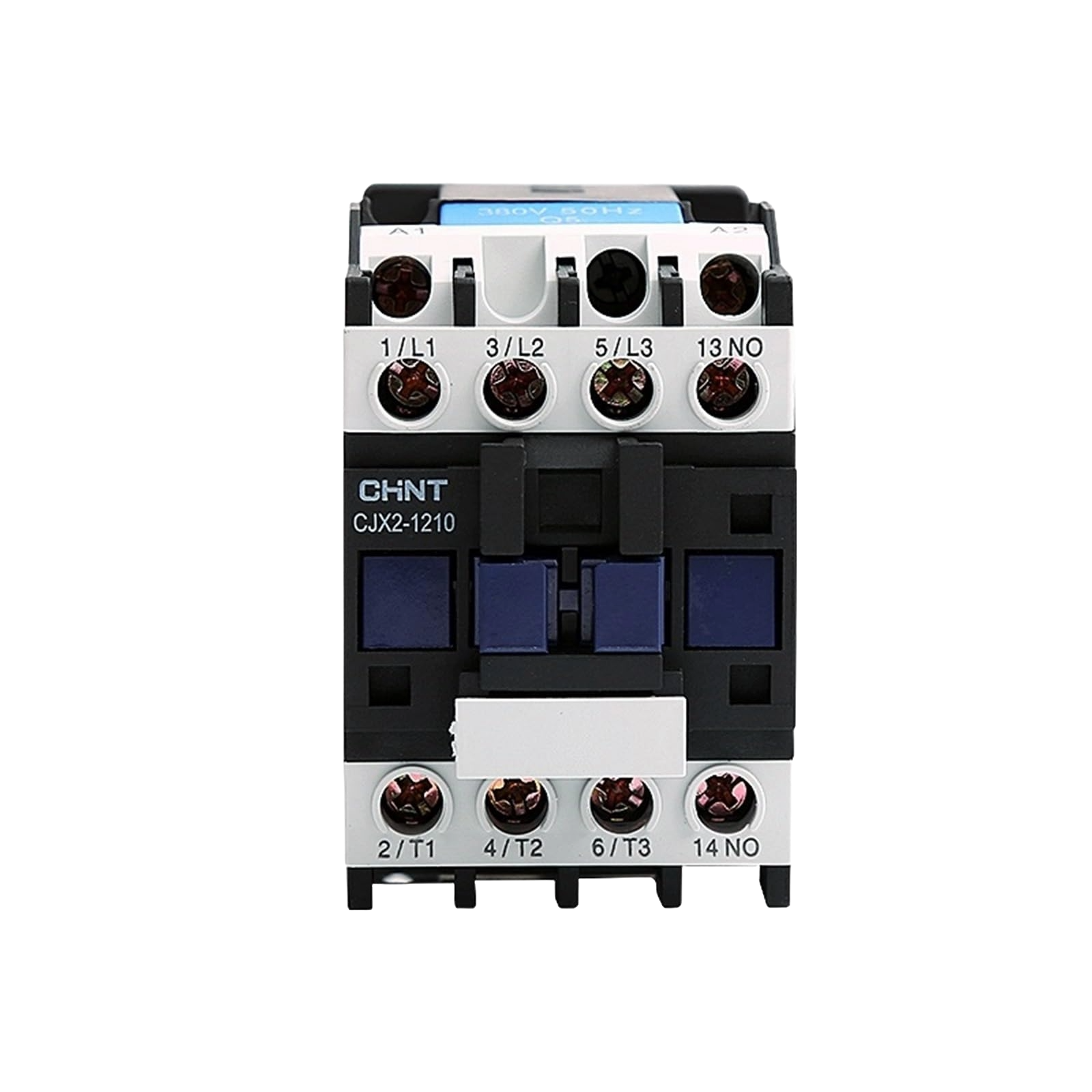
A magnetic contactor is an electromechanical switch used for switching an electrical power circuit. It is essentially a heavy-duty relay with higher current ratings, used for controlling electric motors and other high-power loads in industrial and commercial applications. Contactors come in various sizes and configurations, but they all operate on the same basic principle: an electromagnetic coil is energized to create a magnetic field, which pulls in a set of contacts to make or break the circuit.
Explore Projects Built with magnetic contactor

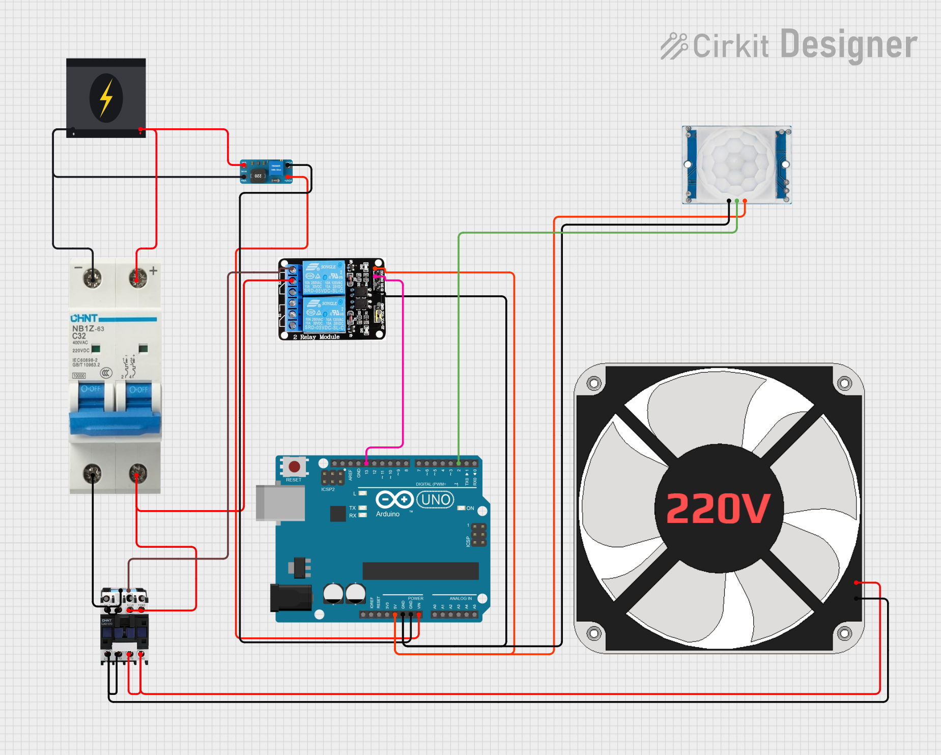


Explore Projects Built with magnetic contactor
Common Applications and Use Cases
- Motor control and starting
- Lighting control systems
- Heating systems
- Power supply control
- Automation systems
Technical Specifications
Key Technical Details
- Rated Voltage: The maximum voltage the contactor can handle.
- Rated Current: The maximum current the contactor can conduct.
- Power Ratings: The maximum power the contactor can switch.
- Coil Voltage: The operating voltage of the electromagnetic coil.
- Contact Configuration: Normally open (NO) or normally closed (NC).
Pin Configuration and Descriptions
| Pin Number | Description | Type |
|---|---|---|
| 1 | Coil Positive | Input |
| 2 | Coil Negative | Input |
| 3 | Common Contact | Output |
| 4 | Normally Open (NO) | Output |
| 5 | Normally Closed (NC) | Output |
Usage Instructions
How to Use the Component in a Circuit
- Power Supply: Ensure that the coil is supplied with the correct voltage as per the contactor's specifications.
- Load Connection: Connect the load to the NO or NC contacts depending on whether you want the load to be energized when the coil is activated or not.
- Control Signal: Use a control signal (e.g., from a push button or a control relay) to energize the coil.
Important Considerations and Best Practices
- Always de-energize the circuit before working on it.
- Use appropriate cable sizes for the load to prevent overheating.
- Ensure that the contactor's ratings exceed the requirements of the load.
- Regularly inspect the contactor for signs of wear or damage.
Troubleshooting and FAQs
Common Issues Users Might Face
- Contactor Does Not Operate: Check the coil voltage and control circuit.
- Contacts Not Making Proper Connection: Inspect for dirt or damage on the contacts.
- Overheating: Ensure the load does not exceed the contactor's ratings.
Solutions and Tips for Troubleshooting
- Verify that the control circuit is supplying the correct voltage to the coil.
- Clean or replace contacts if they are dirty or damaged.
- Check for loose connections and tighten them to ensure proper conductivity.
FAQs
Q: Can a magnetic contactor be used for DC applications? A: Yes, but ensure the contactor is rated for DC operation.
Q: How often should a contactor be inspected? A: It depends on the usage, but generally every 6 to 12 months.
Q: What is the difference between a contactor and a relay? A: Contactors are designed for high-power applications, while relays are used for lower power signals.
Example Code for Arduino UNO
// Example code to control a magnetic contactor with an Arduino UNO
// Note: This is a conceptual example. A real-world application may require
// additional components and considerations for safety and functionality.

const int contactorCoilPin = 7; // The digital pin connected to the contactor coil

void setup() {
  pinMode(contactorCoilPin, OUTPUT); // Set the contactor coil pin as an output
}

void loop() {
  digitalWrite(contactorCoilPin, HIGH); // Energize the coil to close the contacts
  delay(5000); // Keep the contacts closed for 5 seconds
  digitalWrite(contactorCoilPin, LOW); // De-energize the coil to open the contacts
  delay(5000); // Keep the contacts open for 5 seconds
}
Note: The above code assumes the use of a low-voltage contactor that can be directly driven by an Arduino output pin. In practice, contactors require higher currents and voltages to operate, so a driver circuit or an intermediate relay is typically needed to interface with the Arduino. Always consult the contactor's datasheet and ensure all safety protocols are followed when interfacing with high-power devices.