How to Use SX1262: Examples, Pinouts, and Specs
Introduction
The SX1262 is a long-range, low-power LoRa transceiver designed for wireless communication in Internet of Things (IoT) applications. It operates in the sub-GHz frequency range (ranging from 150 MHz to 960 MHz) and supports various modulation schemes, including LoRa and FSK. This enables robust data transmission over long distances with minimal power consumption, making it ideal for battery-powered devices.
Explore Projects Built with SX1262


Explore Projects Built with SX1262
Common Applications and Use Cases
- Smart metering (e.g., water, gas, and electricity meters)
- Asset tracking and fleet management
- Environmental monitoring (e.g., air quality sensors)
- Industrial automation and control
- Smart agriculture and precision farming
- Home automation and security systems
Technical Specifications
The SX1262 is a highly versatile transceiver with the following key technical details:
| Parameter | Value |
|---|---|
| Frequency Range | 150 MHz to 960 MHz |
| Modulation Schemes | LoRa, FSK, GFSK, MSK, GMSK |
| Output Power | Up to +22 dBm |
| Sensitivity | Down to -148 dBm (LoRa mode) |
| Supply Voltage | 1.8 V to 3.7 V |
| Current Consumption | 4.2 mA (Rx mode), 15 mA (Tx @ +14 dBm) |
| Data Rate | 0.018 kbps to 62.5 kbps (LoRa) |
| Operating Temperature Range | -40°C to +85°C |
| Package Type | QFN 24-pin (4 mm x 4 mm) |
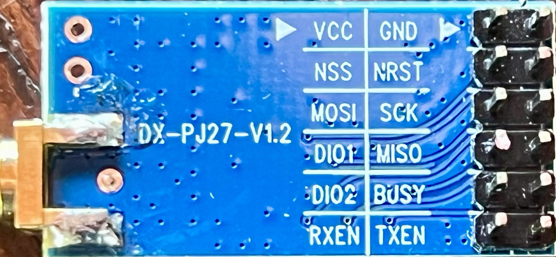
Pin Configuration and Descriptions
The SX1262 comes in a 24-pin QFN package. Below is the pin configuration and description:
| Pin Number | Pin Name | Description |
|---|---|---|
| 1 | GND | Ground connection |
| 2 | RFIO | RF input/output for antenna connection |
| 3 | VDD | Supply voltage input |
| 4 | DIO1 | Digital I/O pin 1 (interrupt or general-purpose) |
| 5 | DIO2 | Digital I/O pin 2 (interrupt or general-purpose) |
| 6 | DIO3 | Digital I/O pin 3 (interrupt or general-purpose) |
| 7 | BUSY | Busy indicator pin |
| 8 | NRESET | Reset pin (active low) |
| 9 | SPI_NSS | SPI chip select |
| 10 | SPI_SCK | SPI clock |
| 11 | SPI_MISO | SPI master-in-slave-out |
| 12 | SPI_MOSI | SPI master-out-slave-in |
| 13-24 | GND | Ground connections (multiple pins for stability) |
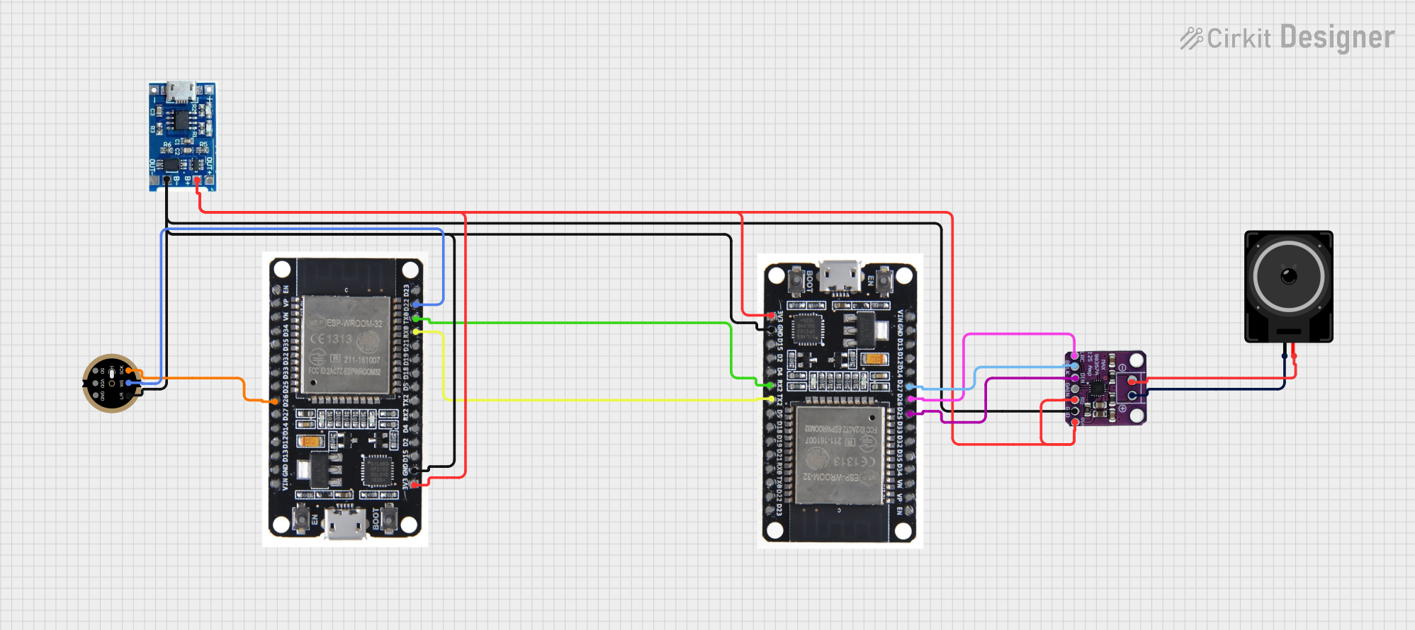
Usage Instructions
The SX1262 is typically used in wireless communication circuits. Below are the steps and best practices for integrating it into your design:
1. Circuit Integration
- Power Supply: Ensure the supply voltage is within the range of 1.8 V to 3.7 V. Use decoupling capacitors (e.g., 100 nF and 10 µF) close to the VDD pin to stabilize the power supply.
- Antenna Connection: Connect the RFIO pin to an appropriate antenna through a matching network to optimize signal transmission and reception.
- SPI Communication: Use the SPI interface (pins SPI_NSS, SPI_SCK, SPI_MISO, and SPI_MOSI) to communicate with a microcontroller.
- GPIO Configuration: Configure the DIO pins as needed for interrupts or general-purpose I/O.
2. Software Configuration
The SX1262 requires a driver or library to configure its registers and manage communication. Below is an example of how to initialize and send data using an Arduino UNO:
#include <SPI.h>

// Define SX1262 pin connections
#define NSS_PIN 10    // SPI chip select
#define RESET_PIN 9   // Reset pin
#define BUSY_PIN 8    // Busy pin
#define DIO1_PIN 7    // DIO1 pin

void setup() {
  // Initialize serial communication for debugging
  Serial.begin(9600);

  // Initialize SPI
  SPI.begin();

  // Configure SX1262 pins
  pinMode(NSS_PIN, OUTPUT);
  pinMode(RESET_PIN, OUTPUT);
  pinMode(BUSY_PIN, INPUT);
  pinMode(DIO1_PIN, INPUT);

  // Reset the SX1262
  digitalWrite(RESET_PIN, LOW);
  delay(10);
  digitalWrite(RESET_PIN, HIGH);
  delay(10);

  // Initialize the SX1262 (example: set to LoRa mode)
  Serial.println("Initializing SX1262...");
  digitalWrite(NSS_PIN, LOW);
  SPI.transfer(0x80); // Example command to set LoRa mode
  digitalWrite(NSS_PIN, HIGH);

  Serial.println("SX1262 initialized.");
}

void loop() {
  // Example: Transmit data
  Serial.println("Transmitting data...");
  digitalWrite(NSS_PIN, LOW);
  SPI.transfer(0x83); // Example command to send data
  SPI.transfer(0x01); // Example payload byte
  digitalWrite(NSS_PIN, HIGH);

  delay(1000); // Wait 1 second before next transmission
}
3. Best Practices
- Use a proper antenna and matching network to maximize range and efficiency.
- Avoid placing the SX1262 near high-frequency noise sources to minimize interference.
- Monitor the BUSY pin to ensure the transceiver is ready before sending commands.
- Use a heat sink or proper ventilation if operating at high output power for extended periods.
Troubleshooting and FAQs
Common Issues and Solutions
No Communication with the SX1262
- Ensure the SPI connections are correct and the microcontroller's SPI settings match the SX1262's requirements.
- Verify that the NSS pin is toggled correctly during SPI communication.
Low Signal Range
- Check the antenna connection and ensure the matching network is properly designed.
- Verify that the output power is configured correctly in the SX1262's registers.
Device Not Responding
- Ensure the SX1262 is properly powered and the reset pin is toggled during initialization.
- Check the BUSY pin to confirm the device is not in a busy state.
High Power Consumption
- Verify that the SX1262 is in sleep mode when not actively transmitting or receiving.
- Reduce the output power if high transmission power is not required.
FAQs
Q: Can the SX1262 operate in both LoRa and FSK modes?
A: Yes, the SX1262 supports both LoRa and FSK modulation schemes, making it versatile for various applications.
Q: What is the maximum range of the SX1262?
A: The range depends on factors such as antenna design, output power, and environmental conditions. In ideal conditions, it can achieve ranges of several kilometers.
Q: Is the SX1262 compatible with Arduino boards?
A: Yes, the SX1262 can be interfaced with Arduino boards using the SPI interface and appropriate libraries.
Q: How do I update the SX1262 firmware?
A: The SX1262 does not require firmware updates as it is a hardware transceiver. Configuration is done via SPI commands.