How to Use Accelerometer & Gyro: Examples, Pinouts, and Specs

Introduction
The Accelerometer & Gyro is a combined sensor that measures both linear acceleration and angular velocity. This dual functionality allows the detection of orientation, movement, and rotation in three-dimensional space. These sensors are widely used in applications such as motion tracking, robotics, gaming, drones, and smartphones.
By combining an accelerometer and a gyroscope, this component provides a comprehensive solution for motion sensing, enabling precise measurements of tilt, orientation, and dynamic movement.
Explore Projects Built with Accelerometer & Gyro

Explore Projects Built with Accelerometer & Gyro
Technical Specifications
Below are the key technical details for a typical Accelerometer & Gyro module (e.g., MPU-6050):
General Specifications
- Supply Voltage: 3.3V to 5V
- Communication Interface: I2C (Inter-Integrated Circuit)
- Acceleration Range: ±2g, ±4g, ±8g, ±16g (configurable)
- Gyroscope Range: ±250°/s, ±500°/s, ±1000°/s, ±2000°/s (configurable)
- Operating Temperature: -40°C to +85°C
- Power Consumption: ~3.9mA (active mode)
Pin Configuration
The Accelerometer & Gyro module typically has the following pinout:
| Pin | Name | Description |
|---|---|---|
| 1 | VCC | Power supply input (3.3V to 5V). |
| 2 | GND | Ground connection. |
| 3 | SCL | I2C clock line for communication. |
| 4 | SDA | I2C data line for communication. |
| 5 | INT | Interrupt pin (optional, used for event-based notifications). |
| 6 | AD0 | Address selection pin (used to set the I2C address of the module). |
Usage Instructions
Connecting the Accelerometer & Gyro to an Arduino UNO
To use the Accelerometer & Gyro module with an Arduino UNO, follow these steps:
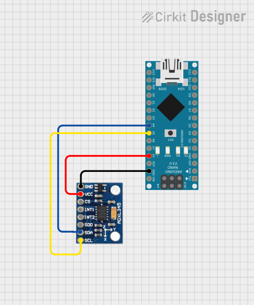
Wiring:
- Connect the
VCCpin of the module to the 5V pin on the Arduino. - Connect the
GNDpin of the module to the GND pin on the Arduino. - Connect the
SCLpin of the module to the A5 pin on the Arduino (I2C clock line). - Connect the
SDApin of the module to the A4 pin on the Arduino (I2C data line).
- Connect the
Install Required Libraries:
- Install the
Wirelibrary (pre-installed with Arduino IDE). - Install the
MPU6050library from the Arduino Library Manager.
- Install the
Example Code: Use the following code to read acceleration and gyroscope data from the module:
#include <Wire.h>
#include <MPU6050.h>

MPU6050 mpu; // Create an MPU6050 object

void setup() {
  Serial.begin(9600); // Initialize serial communication
  Wire.begin();       // Initialize I2C communication

  // Initialize the MPU6050 sensor
  if (!mpu.begin(MPU6050_SCALE_2000DPS, MPU6050_RANGE_2G)) {
    Serial.println("Could not find a valid MPU6050 sensor!");
    while (1); // Halt the program if initialization fails
  }

  Serial.println("MPU6050 initialized successfully!");
}

void loop() {
  // Read acceleration and gyroscope data
  Vector rawAccel = mpu.readRawAccel();
  Vector rawGyro = mpu.readRawGyro();

  // Print acceleration data
  Serial.print("Accel X: "); Serial.print(rawAccel.XAxis);
  Serial.print(" | Accel Y: "); Serial.print(rawAccel.YAxis);
  Serial.print(" | Accel Z: "); Serial.println(rawAccel.ZAxis);

  // Print gyroscope data
  Serial.print("Gyro X: "); Serial.print(rawGyro.XAxis);
  Serial.print(" | Gyro Y: "); Serial.print(rawGyro.YAxis);
  Serial.print(" | Gyro Z: "); Serial.println(rawGyro.ZAxis);

  delay(500); // Wait for 500ms before the next reading
}
Important Considerations
- Power Supply: Ensure the module is powered within its specified voltage range (3.3V to 5V).
- I2C Address: The default I2C address of the module is
0x68. If theAD0pin is connected to VCC, the address changes to0x69. - Mounting Orientation: The module's orientation affects the readings. Ensure it is mounted securely and aligned with the desired axes.
Troubleshooting and FAQs
Common Issues
No Data Output:
- Cause: Incorrect wiring or loose connections.
- Solution: Double-check the wiring and ensure all connections are secure.
Initialization Fails:
- Cause: The module is not detected on the I2C bus.
- Solution: Verify the I2C address and ensure the
SCLandSDAlines are connected properly.
Inconsistent Readings:
- Cause: Vibrations or noise affecting the sensor.
- Solution: Use damping materials to reduce vibrations and ensure stable mounting.
Incorrect Orientation:
- Cause: The module is not aligned with the desired axes.
- Solution: Reorient the module and recalibrate if necessary.
FAQs
Can I use this module with a 3.3V microcontroller?
- Yes, the module supports both 3.3V and 5V power supplies.
How do I calibrate the sensor?
- Calibration can be done using software libraries like
MPU6050or by manually adjusting offsets for each axis.
- Calibration can be done using software libraries like
What is the maximum sampling rate of the module?
- The MPU-6050 supports a maximum sampling rate of 1kHz for both accelerometer and gyroscope data.
By following this documentation, you can effectively integrate and use the Accelerometer & Gyro module in your projects.