How to Use ODB2 Diag: Examples, Pinouts, and Specs
Introduction
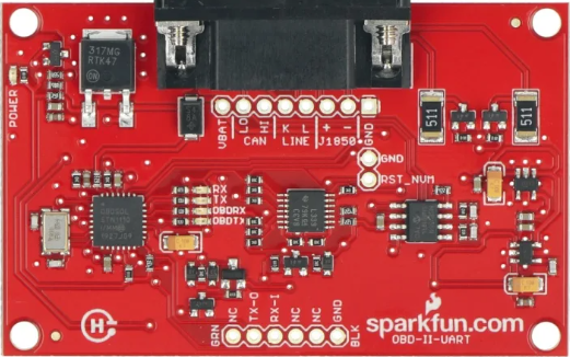
The ODB2 Diag (WIG-09555) is an On-Board Diagnostics II (OBD2) interface device manufactured by SparkFun Electronics. It is designed to provide a communication link between a vehicle's on-board computer and external electronics, such as diagnostic equipment or a data logger. This device is commonly used for vehicle diagnostics, performance monitoring, and as a gateway for telematics applications.
Explore Projects Built with ODB2 Diag


Explore Projects Built with ODB2 Diag
Common Applications and Use Cases
- Vehicle diagnostics and troubleshooting
- Real-time data logging of vehicle parameters
- Performance tuning and monitoring
- Fleet management and vehicle telematics
- Educational purposes for automotive technology
Technical Specifications
Key Technical Details
- Operating Voltage: 5V (from USB)
- Operating Current: 45mA
- Baud Rates: Supports ISO 9141-2, KWP2000, and CAN protocols
- Connector Type: Standard OBD-II connector
- Interface: USB for connection to a computer or microcontroller
Pin Configuration and Descriptions
| Pin Number | Description | Notes |
|---|---|---|
| 1 | Manufacturer discretion | Not connected in WIG-09555 |
| 2 | SAE J1850 Bus+ | Not typically used with WIG-09555 |
| 3 | Manufacturer discretion | Not connected in WIG-09555 |
| 4 | Chassis Ground | Connected to vehicle ground |
| 5 | Signal Ground | Connected to signal ground |
| 6 | CAN High (J-2284) | Used for CAN protocol |
| 7 | ISO 9141-2 K Line | Used for ISO/KWP protocols |
| 8 | Manufacturer discretion | Not connected in WIG-09555 |
| 9 | Manufacturer discretion | Not connected in WIG-09555 |
| 10 | SAE J1850 Bus- | Not typically used with WIG-09555 |
| 11 | Manufacturer discretion | Not connected in WIG-09555 |
| 12 | Manufacturer discretion | Not connected in WIG-09555 |
| 13 | Manufacturer discretion | Not connected in WIG-09555 |
| 14 | CAN Low (J-2284) | Used for CAN protocol |
| 15 | ISO 9141-2 L Line (optional) | Not typically used with WIG-09555 |
| 16 | Battery Power | Connected to vehicle battery |
Usage Instructions
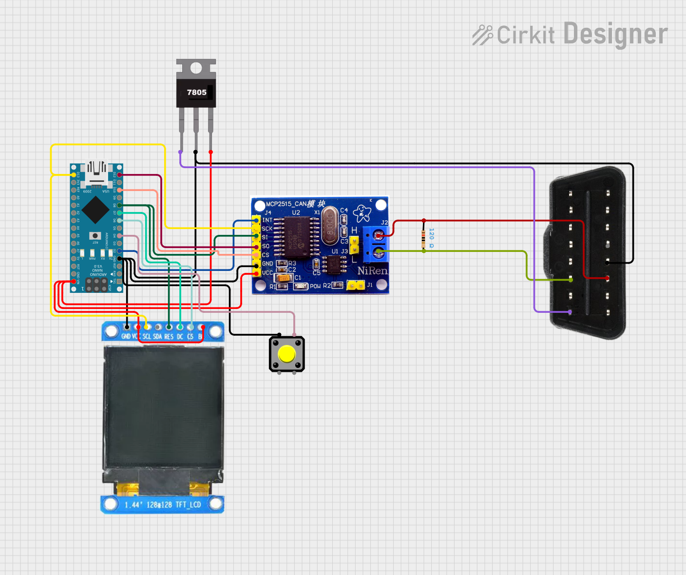
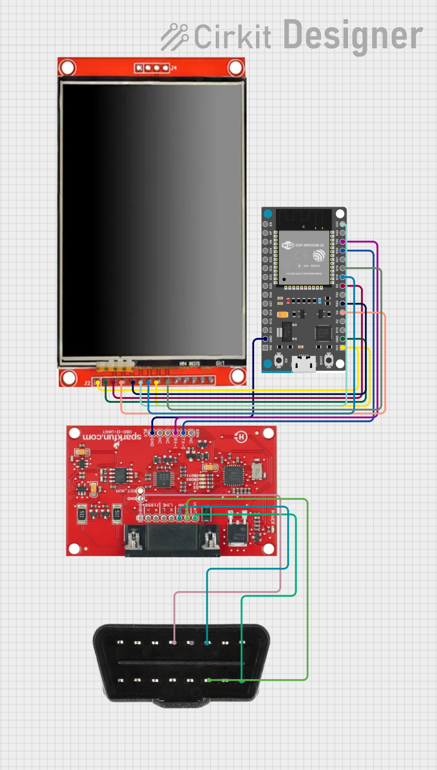
How to Use the Component in a Circuit
Connect to Vehicle:
- Plug the ODB2 Diag device into the vehicle's OBD-II port, typically found under the dashboard.
Connect to Computer:
- Use a USB cable to connect the ODB2 Diag to a computer or a compatible microcontroller like an Arduino UNO.
Install Drivers and Software:
- Ensure that the necessary drivers for the USB interface are installed on the computer.
- Install software capable of communicating with the ODB2 Diag, such as a terminal program or a specialized OBD-II software application.
Establish Communication:
- Open the software and configure it to the correct COM port and baud rate.
- Initiate communication with the vehicle's ECU using the appropriate commands for the desired protocol (ISO 9141-2, KWP2000, or CAN).
Important Considerations and Best Practices
- Vehicle Compatibility: Ensure the vehicle supports OBD-II protocols compatible with the ODB2 Diag.
- Power Supply: The device is powered through the USB connection; ensure the computer or microcontroller can supply adequate current.
- Protocol Selection: Know the protocol used by the vehicle's ECU to select the correct settings in your software.
- Safety: When working with a vehicle's electrical system, always take appropriate safety precautions to prevent injury or damage to the vehicle.
Troubleshooting and FAQs
Common Issues Users Might Face
- Device Not Recognized: Check USB connections, ensure drivers are installed, and try a different USB port.
- No Communication with Vehicle: Verify that the vehicle's ignition is on and that the ODB2 Diag is properly connected to the OBD-II port.
- Incorrect Data: Ensure that the software is configured for the correct protocol and that there are no loose connections.
Solutions and Tips for Troubleshooting
- Driver Issues: Visit SparkFun's website for the latest drivers and installation guides.
- Software Configuration: Consult the software's documentation for setup instructions and troubleshooting tips.
- Check Connections: Inspect the OBD-II port and USB cable for any signs of damage or poor connection.
FAQs
Q: Can the ODB2 Diag be used with any vehicle?
- A: It can be used with most vehicles manufactured after 1996, as they are required to have an OBD-II port.
Q: What software can I use with the ODB2 Diag?
- A: There are various OBD-II software applications available, both free and paid, that are compatible with the ODB2 Diag.
Q: How do I know if my vehicle uses CAN, ISO 9141-2, or KWP2000?
- A: This information is typically found in the vehicle's service manual or can be determined by an OBD-II scan tool.
For further assistance, contact SparkFun's technical support or refer to the community forums for shared user experiences and solutions.
Please note that this documentation is a general guide and may not cover all aspects or specific scenarios encountered when using the ODB2 Diag device. Always refer to the manufacturer's official documentation and resources for the most accurate and detailed information.