How to Use BMI270: Examples, Pinouts, and Specs
Introduction
The BMI270 is a low-power, 6-axis inertial measurement unit (IMU) that integrates a 3-axis accelerometer and a 3-axis gyroscope. It is designed for motion sensing applications, making it ideal for wearable devices, Internet of Things (IoT) applications, and other motion-based systems. The BMI270 offers high precision, low power consumption, and advanced features such as step counting and activity recognition, making it a versatile choice for developers.
Explore Projects Built with BMI270

Explore Projects Built with BMI270
Common Applications and Use Cases
- Fitness trackers and smartwatches
- Augmented reality (AR) and virtual reality (VR) devices
- IoT devices for motion detection and monitoring
- Robotics and drone stabilization
- Gesture recognition systems
Technical Specifications
The BMI270 is a highly capable IMU with the following key specifications:
| Parameter | Value |
|---|---|
| Operating Voltage | 1.71V to 3.6V |
| Power Consumption | 30 µA (accelerometer in low-power mode) |
| Accelerometer Range | ±2g, ±4g, ±8g, ±16g |
| Gyroscope Range | ±125°/s, ±250°/s, ±500°/s, ±1000°/s, ±2000°/s |
| Communication Interface | I2C, SPI |
| Operating Temperature Range | -40°C to +85°C |
| Dimensions | 2.5 mm × 3.0 mm × 0.8 mm |
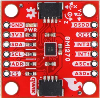
Pin Configuration and Descriptions
The BMI270 is typically available in a 14-pin LGA package. Below is the pin configuration:
| Pin Number | Pin Name | Description |
|---|---|---|
| 1 | VDD | Power supply (1.71V to 3.6V) |
| 2 | VDDIO | I/O voltage supply |
| 3 | GND | Ground |
| 4 | CS | Chip select for SPI (active low) |
| 5 | SDO/SA0 | SPI data out / I2C address selection |
| 6 | SCL/SCK | I2C clock / SPI clock |
| 7 | SDA/SDI | I2C data / SPI data in |
| 8 | INT1 | Interrupt 1 output |
| 9 | INT2 | Interrupt 2 output |
| 10-14 | NC | Not connected (leave floating) |
Usage Instructions
How to Use the BMI270 in a Circuit
- Power Supply: Connect the VDD pin to a 1.8V to 3.3V power source and the GND pin to ground. Ensure the VDDIO pin matches the logic level of your microcontroller (e.g., 3.3V or 1.8V).
- Communication Interface: Choose between I2C or SPI for communication:
- For I2C, connect the SCL and SDA pins to the corresponding I2C pins on your microcontroller. Use pull-up resistors (typically 4.7kΩ) on both lines.
- For SPI, connect the CS, SCK, SDI, and SDO pins to the corresponding SPI pins on your microcontroller.
- Interrupts: Use the INT1 and INT2 pins to receive motion or activity interrupts from the BMI270.
- Configuration: Initialize the BMI270 by configuring its registers via the chosen communication interface. Set the desired accelerometer and gyroscope ranges, output data rates, and enable any required features (e.g., step counting).
Important Considerations and Best Practices
- Power Management: Use the low-power mode for battery-powered applications to extend battery life.
- Mounting: Place the BMI270 on a stable PCB with minimal vibration to ensure accurate measurements.
- I2C Address: The I2C address of the BMI270 is determined by the state of the SDO/SA0 pin. Connect it to GND for the default address (0x68) or to VDDIO for an alternate address (0x69).
- Filtering: Use digital filtering to reduce noise in accelerometer and gyroscope readings.
Example Code for Arduino UNO
Below is an example of how to interface the BMI270 with an Arduino UNO using I2C:
#include <Wire.h>

#define BMI270_I2C_ADDRESS 0x68 // Default I2C address of BMI270

void setup() {
  Wire.begin(); // Initialize I2C communication
  Serial.begin(9600); // Initialize serial communication for debugging

  // Configure BMI270
  Wire.beginTransmission(BMI270_I2C_ADDRESS);
  Wire.write(0x7E); // Register address for command register
  Wire.write(0x11); // Command to initialize accelerometer and gyroscope
  Wire.endTransmission();
  delay(100); // Wait for initialization to complete

  Serial.println("BMI270 initialized.");
}

void loop() {
  // Read accelerometer data
  Wire.beginTransmission(BMI270_I2C_ADDRESS);
  Wire.write(0x12); // Register address for accelerometer data
  Wire.endTransmission(false);
  Wire.requestFrom(BMI270_I2C_ADDRESS, 6); // Request 6 bytes (X, Y, Z)

  if (Wire.available() == 6) {
    int16_t accelX = (Wire.read() | (Wire.read() << 8));
    int16_t accelY = (Wire.read() | (Wire.read() << 8));
    int16_t accelZ = (Wire.read() | (Wire.read() << 8));

    Serial.print("Accel X: "); Serial.print(accelX);
    Serial.print(" Y: "); Serial.print(accelY);
    Serial.print(" Z: "); Serial.println(accelZ);
  }

  delay(500); // Delay for readability
}
Troubleshooting and FAQs
Common Issues and Solutions
No Communication with the BMI270
- Cause: Incorrect I2C address or wiring.
- Solution: Verify the I2C address (default is 0x68) and check all connections, including pull-up resistors on the I2C lines.
Inaccurate Sensor Readings
- Cause: Excessive vibration or poor PCB layout.
- Solution: Ensure the BMI270 is mounted on a stable surface and away from vibration sources. Use filtering to reduce noise.
Interrupts Not Triggering
- Cause: Interrupts not configured correctly.
- Solution: Check the interrupt configuration registers and ensure the INT1/INT2 pins are connected properly.
FAQs
Q: Can the BMI270 operate at 5V?
A: No, the maximum operating voltage is 3.6V. Use a voltage regulator or level shifter if interfacing with a 5V system.Q: How do I change the accelerometer range?
A: Write to the accelerometer configuration register (0x40) to set the desired range (e.g., ±2g, ±4g).Q: Is the BMI270 suitable for high-temperature environments?
A: Yes, it operates reliably within a temperature range of -40°C to +85°C.