How to Use LAN8720: Examples, Pinouts, and Specs
Introduction
The LAN8720 is a low-power, highly integrated Ethernet transceiver that supports 10/100 Mbps Ethernet communication. It is designed to provide a simple and efficient interface for connecting microcontrollers or processors to Ethernet networks. The component is widely used in industrial and consumer electronics applications, including IoT devices, embedded systems, and networked sensors. Its compact design and low power consumption make it an ideal choice for space-constrained and energy-sensitive projects.
Explore Projects Built with LAN8720


Explore Projects Built with LAN8720
Common Applications
- IoT devices requiring Ethernet connectivity
- Embedded systems with network communication
- Industrial automation and control systems
- Consumer electronics with Ethernet interfaces
- Networked sensors and data acquisition systems
Technical Specifications
Key Technical Details
- Ethernet Standards: IEEE 802.3/802.3u (10BASE-T/100BASE-TX)
- Data Rates: 10 Mbps and 100 Mbps
- Power Supply Voltage: 3.3V
- Power Consumption: Low-power operation with energy-efficient features
- Interface: MII (Media Independent Interface) and RMII (Reduced Media Independent Interface)
- Operating Temperature Range: -40°C to +85°C
- Package: 24-pin QFN (Quad Flat No-lead)
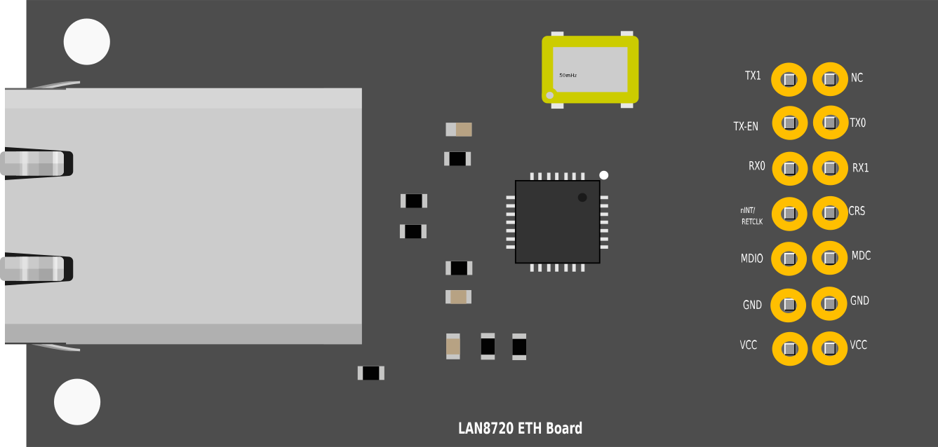
Pin Configuration and Descriptions
The LAN8720 has 24 pins, with the following key pin functions:
| Pin Number | Pin Name | Description |
|---|---|---|
| 1 | TXP | Transmit Data Positive |
| 2 | TXN | Transmit Data Negative |
| 3 | VDDIO | Digital I/O Power Supply (3.3V) |
| 4 | RXN | Receive Data Negative |
| 5 | RXP | Receive Data Positive |
| 6 | GND | Ground |
| 7 | RBIAS | External Bias Resistor Connection |
| 8 | VDDCR | Core Power Supply (1.2V) |
| 9 | XTAL1 | Crystal Input or External Clock Input |
| 10 | XTAL2 | Crystal Output |
| 11 | MDC | Management Data Clock (for MDIO interface) |
| 12 | MDIO | Management Data Input/Output (for PHY configuration) |
| 13 | CRS_DV | Carrier Sense/Receive Data Valid (RMII mode) |
| 14 | RXD0 | Receive Data Bit 0 |
| 15 | RXD1 | Receive Data Bit 1 |
| 16 | RXER | Receive Error |
| 17 | TXEN | Transmit Enable |
| 18 | TXD0 | Transmit Data Bit 0 |
| 19 | TXD1 | Transmit Data Bit 1 |
| 20 | GND | Ground |
| 21 | VDDIO | Digital I/O Power Supply (3.3V) |
| 22 | LED1 | Configurable LED Output 1 (e.g., Link/Activity Indicator) |
| 23 | LED2 | Configurable LED Output 2 (e.g., Speed Indicator) |
| 24 | RESET_N | Active Low Reset Input |
Usage Instructions
How to Use the LAN8720 in a Circuit
- Power Supply: Connect the VDDIO pins to a 3.3V power source and the GND pins to ground. Ensure proper decoupling capacitors are placed near the power pins for stable operation.
- Clock Source: Provide a 25 MHz crystal oscillator or an external clock signal to the XTAL1 and XTAL2 pins.
- Bias Resistor: Connect a precision 4.87 kΩ resistor between the RBIAS pin and ground to set the internal bias currents.
- Ethernet Signals: Connect the TXP/TXN and RXP/RXN pins to the Ethernet transformer and RJ45 connector for Ethernet communication.
- Microcontroller Interface: Use the RMII or MII interface to connect the LAN8720 to the microcontroller or processor. Ensure proper pin mapping for TXD, RXD, TXEN, CRS_DV, and other control signals.
- Configuration: Use the MDIO and MDC pins to configure the PHY registers if needed. Default settings typically work for most applications.
- LED Indicators: Connect LEDs to the LED1 and LED2 pins for status indication (e.g., link status, activity, or speed).
Important Considerations and Best Practices
- Ensure the Ethernet transformer is properly matched to the LAN8720 for optimal signal integrity.
- Use proper PCB layout techniques to minimize noise and interference, especially for high-speed signals.
- Place decoupling capacitors close to the power pins to reduce power supply noise.
- If using RMII mode, ensure the microcontroller supports the RMII interface and configure the clock accordingly.
- Use pull-up or pull-down resistors on configuration pins as required by the application.
Example: Connecting LAN8720 to Arduino UNO
The LAN8720 can be connected to an Arduino UNO using an RMII interface. Below is an example code snippet for initializing the LAN8720 with an Arduino-compatible Ethernet library:
#include <Ethernet.h> // Include the Ethernet library

// MAC address and IP address for the Ethernet module
byte mac[] = { 0xDE, 0xAD, 0xBE, 0xEF, 0xFE, 0xED };
IPAddress ip(192, 168, 1, 100);

void setup() {
  // Start the serial communication for debugging
  Serial.begin(9600);
  while (!Serial) {
    ; // Wait for the serial port to connect
  }

  // Initialize the Ethernet connection
  if (Ethernet.begin(mac) == 0) {
    Serial.println("Failed to configure Ethernet using DHCP");
    // Try a static IP address if DHCP fails
    Ethernet.begin(mac, ip);
  }

  // Print the assigned IP address
  Serial.print("Ethernet initialized. IP address: ");
  Serial.println(Ethernet.localIP());
}

void loop() {
  // Add your Ethernet communication code here
}
Troubleshooting and FAQs
Common Issues and Solutions
No Ethernet Link Detected:
- Check the RJ45 connector and Ethernet cable for proper connection.
- Verify the TXP/TXN and RXP/RXN connections to the Ethernet transformer.
- Ensure the LAN8720 is powered correctly and the RESET_N pin is not held low.
Microcontroller Cannot Communicate with LAN8720:
- Verify the RMII or MII interface connections between the microcontroller and LAN8720.
- Check the clock source (25 MHz) and ensure it is stable and within tolerance.
- Use the MDIO/MDC interface to read the PHY registers and confirm proper initialization.
High Power Consumption:
- Ensure the RBIAS resistor is correctly connected and has the correct value (4.87 kΩ).
- Check for short circuits or incorrect connections on the PCB.
LED Indicators Not Working:
- Verify the LED1 and LED2 pin connections and ensure the LEDs are not damaged.
- Check the PHY configuration registers to confirm the LED functionality is enabled.
FAQs
Q: Can the LAN8720 operate at 5V?
A: No, the LAN8720 is designed to operate at 3.3V. Applying 5V may damage the component.
Q: What is the maximum cable length supported by the LAN8720?
A: The LAN8720 supports Ethernet cable lengths up to 100 meters, as per the IEEE 802.3 standard.
Q: Can I use the LAN8720 with a 16 MHz microcontroller?
A: Yes, but ensure the microcontroller supports the RMII interface and can provide the required 50 MHz clock for RMII operation.
Q: How do I reset the LAN8720?
A: Pull the RESET_N pin low for at least 1 µs and then release it to reset the LAN8720.