How to Use REX-100: Examples, Pinouts, and Specs
Introduction
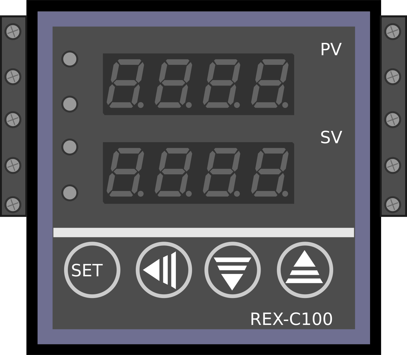
The REX-100 is a precision temperature controller designed for industrial applications. It features a digital display for real-time temperature monitoring, programmable settings for customized operation, and multiple output options to control heating elements or cooling systems. This versatile component is ideal for maintaining precise temperature control in processes such as manufacturing, laboratory experiments, and HVAC systems.
Explore Projects Built with REX-100


Explore Projects Built with REX-100
Common Applications and Use Cases
- Industrial heating and cooling systems
- Laboratory temperature regulation
- Food processing and storage
- HVAC (Heating, Ventilation, and Air Conditioning) systems
- Plastic molding and extrusion processes
Technical Specifications
Key Technical Details
| Parameter | Value |
|---|---|
| Input Voltage | 100-240V AC, 50/60 Hz |
| Temperature Range | -50°C to 1300°C (sensor-dependent) |
| Display Type | 4-digit LED display |
| Control Output Options | Relay, Voltage Pulse, or 4-20mA |
| Sensor Compatibility | Thermocouples (e.g., K, J, T) or RTD (e.g., PT100) |
| Accuracy | ±0.5% of full scale |
| Operating Temperature | 0°C to 50°C |
| Dimensions | 48mm x 48mm x 110mm |
| Weight | 150g |
Pin Configuration and Descriptions
The REX-100 has a terminal block for wiring connections. Below is the pin configuration:
| Pin Number | Description | Notes |
|---|---|---|
| 1 | Power Input (L) | Connect to live AC line |
| 2 | Power Input (N) | Connect to neutral AC line |
| 3 | Sensor Input (+) | Positive terminal of the sensor |
| 4 | Sensor Input (-) | Negative terminal of the sensor |
| 5 | Control Output (Relay NO) | Normally open relay contact |
| 6 | Control Output (Relay COM) | Common relay contact |
| 7 | Control Output (Relay NC) | Normally closed relay contact |
| 8 | Voltage Pulse Output (+) | Positive terminal for voltage pulse |
| 9 | Voltage Pulse Output (-) | Negative terminal for voltage pulse |
| 10 | 4-20mA Output (+) | Positive terminal for current loop |
| 11 | 4-20mA Output (-) | Negative terminal for current loop |
Usage Instructions
How to Use the REX-100 in a Circuit
- Power Connection: Connect the REX-100 to a 100-240V AC power source using pins 1 (L) and 2 (N).
- Sensor Connection: Attach a compatible temperature sensor (e.g., thermocouple or RTD) to pins 3 (+) and 4 (-).
- Control Output:
- For relay control, use pins 5, 6, and 7 to connect the heating or cooling element.
- For voltage pulse output, use pins 8 and 9.
- For 4-20mA current loop control, use pins 10 and 11.
- Programming: Use the front panel buttons to set the desired temperature, control mode (e.g., heating or cooling), and other parameters.
- Operation: Once powered on and configured, the REX-100 will monitor the temperature and adjust the output to maintain the setpoint.
Important Considerations and Best Practices
- Ensure the sensor type matches the REX-100's configuration (e.g., K-type thermocouple or PT100 RTD).
- Use proper electrical insulation and grounding to prevent interference or damage.
- Avoid exposing the REX-100 to excessive moisture, dust, or vibration.
- Regularly calibrate the temperature sensor for accurate readings.
- For safety, use a fuse or circuit breaker on the power input line.
Example: Connecting to an Arduino UNO
The REX-100 can be used with an Arduino UNO to monitor and log temperature data. Below is an example code snippet for reading the temperature via a 4-20mA current loop sensor connected to the REX-100.
// Example: Reading temperature from REX-100 using Arduino UNO
// The REX-100 outputs a 4-20mA signal proportional to temperature.
// A 250-ohm resistor is used to convert the current to a voltage (1-5V).

const int analogPin = A0; // Analog pin connected to the resistor
float voltage = 0.0;      // Variable to store the measured voltage
float temperature = 0.0;  // Variable to store the calculated temperature

void setup() {
  Serial.begin(9600); // Initialize serial communication
}

void loop() {
  // Read the analog voltage (0-1023 corresponds to 0-5V)
  int analogValue = analogRead(analogPin);
  voltage = (analogValue / 1023.0) * 5.0;

  // Convert voltage to temperature (example: 1V = 0°C, 5V = 100°C)
  temperature = (voltage - 1.0) * 25.0; // Adjust based on REX-100 scaling

  // Print the temperature to the Serial Monitor
  Serial.print("Temperature: ");
  Serial.print(temperature);
  Serial.println(" °C");

  delay(1000); // Wait 1 second before the next reading
}
Troubleshooting and FAQs
Common Issues and Solutions
No Display or Power:
- Check the power connections to pins 1 (L) and 2 (N).
- Verify the power source voltage is within the specified range (100-240V AC).
- Inspect the fuse or circuit breaker for faults.
Incorrect Temperature Reading:
- Ensure the sensor is properly connected to pins 3 (+) and 4 (-).
- Verify the sensor type matches the REX-100's configuration.
- Check for sensor damage or calibration errors.
Control Output Not Working:
- Confirm the output wiring matches the selected control mode (relay, voltage pulse, or 4-20mA).
- Verify the setpoint and control parameters are correctly programmed.
- Inspect the connected heating or cooling element for faults.
Interference or Noise in Readings:
- Use shielded cables for sensor connections.
- Ensure proper grounding of the REX-100 and connected devices.
- Avoid running sensor cables near high-power lines or motors.
FAQs
Q: Can the REX-100 control both heating and cooling systems?
A: Yes, the REX-100 can be configured for either heating or cooling control, depending on the application.
Q: What is the maximum load the relay output can handle?
A: The relay output can handle up to 3A at 250V AC or 3A at 30V DC.
Q: How do I reset the REX-100 to factory settings?
A: Refer to the user manual for the specific button sequence to restore factory settings.
Q: Can I use the REX-100 with a DC power supply?
A: No, the REX-100 requires an AC power supply within the range of 100-240V AC.