How to Use MPU-9250/6500/9255: Examples, Pinouts, and Specs
Introduction
The MPU-9250/6500/9255 is a highly integrated 9-axis motion tracking device that combines a 3-axis gyroscope, a 3-axis accelerometer, and a 3-axis magnetometer in a single compact package. This component is widely used for applications requiring precise orientation, motion sensing, and environmental awareness. Its small size, low power consumption, and high performance make it ideal for use in robotics, drones, wearable devices, gaming controllers, and augmented reality systems.
Explore Projects Built with MPU-9250/6500/9255

Explore Projects Built with MPU-9250/6500/9255
Common Applications:
- Robotics for motion tracking and navigation
- Drones for stabilization and flight control
- Wearable devices for fitness tracking and gesture recognition
- Gaming controllers for motion-based input
- Augmented and virtual reality systems for orientation sensing
Technical Specifications
The MPU-9250/6500/9255 offers a range of features and specifications that make it suitable for a variety of motion sensing applications.
Key Technical Details:
- Gyroscope Range: ±250, ±500, ±1000, ±2000 degrees/second
- Accelerometer Range: ±2g, ±4g, ±8g, ±16g
- Magnetometer Range: ±4800 µT
- Communication Interface: I²C (up to 400 kHz) and SPI (up to 1 MHz)
- Operating Voltage: 2.4V to 3.6V
- Power Consumption:
- Gyroscope: 3.2 mA
- Accelerometer: 450 µA
- Magnetometer: 280 µA
- Operating Temperature: -40°C to +85°C
- Package Dimensions: 3x3x1 mm (QFN package)
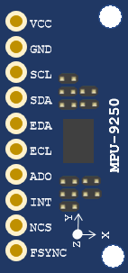
Pin Configuration and Descriptions:
The MPU-9250/6500/9255 has 24 pins. Below is a table describing the key pins:
| Pin Name | Type | Description |
|---|---|---|
| VDD | Power Supply | Main power supply (2.4V to 3.6V). |
| VDDIO | Power Supply | I/O voltage supply. |
| GND | Ground | Ground connection. |
| SCL | Input | I²C clock line. |
| SDA | Input/Output | I²C data line. |
| CS | Input | Chip select for SPI communication (active low). |
| INT | Output | Interrupt signal output. |
| FSYNC | Input | Frame synchronization input. |
| AUX_DA | Input/Output | Auxiliary I²C data line for external sensors. |
| AUX_CL | Input | Auxiliary I²C clock line for external sensors. |
| RESV | Reserved | Reserved pins. Must be left unconnected or connected as per the datasheet. |
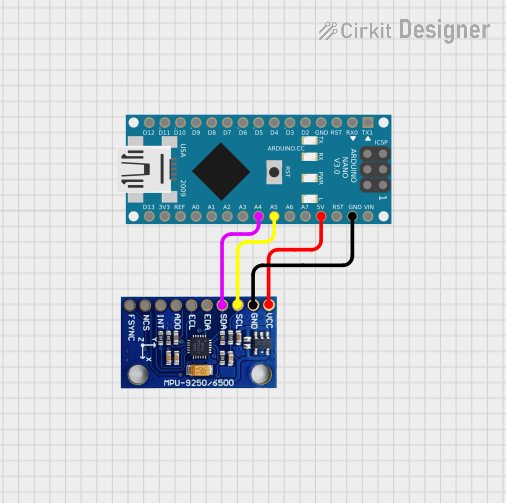
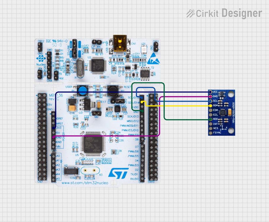
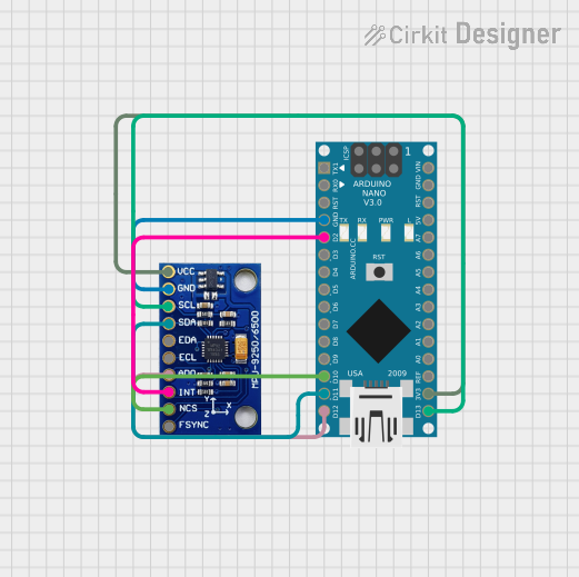
Usage Instructions
How to Use the MPU-9250/6500/9255 in a Circuit:
- Power Supply: Connect the VDD pin to a 3.3V power source and GND to ground. If using a 5V system, use a voltage regulator to step down the voltage.
- Communication Interface:
- For I²C: Connect the SCL and SDA pins to the corresponding I²C lines on your microcontroller. Use pull-up resistors (typically 4.7kΩ) on both lines.
- For SPI: Connect the CS, SCL, and SDA pins to the SPI lines on your microcontroller.
- Interrupts: If needed, connect the INT pin to a GPIO pin on your microcontroller to handle interrupts.
- External Sensors: If using external sensors, connect them to the AUX_DA and AUX_CL pins.
Important Considerations:
- Bypass Capacitors: Place a 0.1 µF ceramic capacitor close to the VDD pin to stabilize the power supply.
- Pull-Up Resistors: Ensure proper pull-up resistors are used for I²C communication.
- Magnetometer Calibration: Perform a calibration routine to account for hard and soft iron distortions in the magnetometer.
- Orientation: Mount the sensor on a stable surface to minimize vibrations and noise.
Example Code for Arduino UNO:
Below is an example of how to interface the MPU-9250 with an Arduino UNO using I²C:
#include <Wire.h>

// MPU-9250 I2C address
#define MPU9250_ADDRESS 0x68

// Register addresses
#define WHO_AM_I 0x75
#define PWR_MGMT_1 0x6B
#define ACCEL_XOUT_H 0x3B

void setup() {
  Wire.begin(); // Initialize I2C communication
  Serial.begin(9600); // Initialize serial communication

  // Wake up the MPU-9250
  Wire.beginTransmission(MPU9250_ADDRESS);
  Wire.write(PWR_MGMT_1); // Access power management register
  Wire.write(0x00); // Set to zero to wake up the sensor
  Wire.endTransmission();

  // Check if the sensor is connected
  Wire.beginTransmission(MPU9250_ADDRESS);
  Wire.write(WHO_AM_I); // Access WHO_AM_I register
  Wire.endTransmission();
  Wire.requestFrom(MPU9250_ADDRESS, 1);
  if (Wire.available()) {
    byte whoAmI = Wire.read();
    Serial.print("MPU-9250 WHO_AM_I: 0x");
    Serial.println(whoAmI, HEX);
  }
}

void loop() {
  // Read accelerometer data
  Wire.beginTransmission(MPU9250_ADDRESS);
  Wire.write(ACCEL_XOUT_H); // Start reading from ACCEL_XOUT_H register
  Wire.endTransmission();
  Wire.requestFrom(MPU9250_ADDRESS, 6); // Request 6 bytes (X, Y, Z)

  if (Wire.available() == 6) {
    int16_t accelX = (Wire.read() << 8) | Wire.read();
    int16_t accelY = (Wire.read() << 8) | Wire.read();
    int16_t accelZ = (Wire.read() << 8) | Wire.read();

    Serial.print("Accel X: ");
    Serial.print(accelX);
    Serial.print(" | Accel Y: ");
    Serial.print(accelY);
    Serial.print(" | Accel Z: ");
    Serial.println(accelZ);
  }

  delay(500); // Delay for readability
}
Troubleshooting and FAQs
Common Issues:
No Response from the Sensor:
- Cause: Incorrect I²C address or wiring.
- Solution: Verify the I²C address (default is 0x68) and check all connections.
Inconsistent Readings:
- Cause: Lack of calibration or external interference.
- Solution: Perform a calibration routine for the accelerometer, gyroscope, and magnetometer.
High Noise in Data:
- Cause: Vibrations or unstable power supply.
- Solution: Mount the sensor on a stable surface and use bypass capacitors near the power pins.
Magnetometer Not Working:
- Cause: Magnetometer disabled in the configuration.
- Solution: Ensure the magnetometer is enabled in the initialization code.
FAQs:
Q: Can the MPU-9250/6500/9255 operate at 5V?
A: No, the sensor operates at 2.4V to 3.6V. Use a voltage regulator or level shifter for 5V systems.Q: How do I calibrate the magnetometer?
A: Rotate the sensor in all directions to collect data, then use a calibration algorithm to correct for distortions.Q: What is the difference between the MPU-9250, MPU-6500, and MPU-9255?
A: The MPU-9250 and MPU-9255 include a magnetometer, while the MPU-6500 does not. The MPU-9255 has improved magnetometer performance compared to the MPU-9250.